These things are a little miracle. A jumpstarter you hold in one hand that I used to start the 6.7 liter diesel in my truck. How can this be? The truck has two lead acid batteries the size of toaster ovens. I left the damned lights on at a race track. Went to start it and click, click… …nothing. I took the little compressor/battery bank/flashlight/jumper from my motorcycle and connected it. Once it gave me a green light I hit the switch. Boom, it turned over faster than it does on a fully charged monster dual battery setup. I did NOT expect that to work. How is that possible?
The simple answer–the massive C rating and low internal resistance of NMC Lithium batteries. C rating means how fast you can charge it, so maybe we should call it a D rating since we care about discharging more than charging, but the number is the same, and that’s not how it’s described technically. So the C rating of a typical NMC battery used in a jumpstarter pack is 15-30C and in some cases 100C for short periods. NMC batteries are generally used since they store a lot of power in a small size and handle high burst rate discharges. So if pack is rated at 5000mah (milliamp-hours, so 5Ah) a 30C discharge rate means it can supply 150Amps, if it can do 100C in a burst that’s 500amps. Not for long of course. Even at 30C discharge a 5Ah battery cranking a motorcycle at 150 amps will only last about 2 minutes. In reality a start lasting 10 seconds at 150 amps (150 A × 10 s = 1,500 amp-seconds ÷ 3,600 = about 0.42 Ah (417 mAh)) chews up about 1/10th of the capacity–you get ten tries…maybe. But usually one is enough.
Here’s how they work–it’s more complicated than you think.
The box you plug into the compressor of main unit or the bulge in the middle of the cable contains a relay or MOSFET switch that only connects the pack when everything checks out and you turn the switch to start. It provides: –Reverse-polarity protection, so the clamps don’t spark or blow the guts out of your jumper box if you get them backwards. –Short-circuit and overcurrent protection. –Back-feed protection, so the vehicle’s alternator can’t charge the pack. –Battery detection: it won’t switch on until it senses a battery at the clamps. A “boost” or override button bypasses this when the vehicle’s battery is almost completely dead. Once that little box is happy it turns the light green–but that’s about all that happens. The battery is in parallel with your dead or semi-dead battery, but you don’t want it to charge the battery, you want to start the vehicle. So when you turn the switch to start, the box senses the current draw (actually, the voltage drop) and triggers the jumper either closing a relay or firing some hefty MOSFETs. Bam–you have 150 or more amps going though some fairly wimpy wires and clamps. If that current flowed for more than a few seconds stuff would melt, but it doesn’t, so all good–apparently. I’m sure this isn’t violating the laws of physics, but it’s pushing at the edge of the box.
I put a clamp-on hall effect ammeter that can measure and lock inrush current on my little jumper box. On my F350 diesel truck I measured 468 amps with a device the manufacturer claimed was good for 150, so I’d say Your mileage will vary. Started my F350 just fine. I don’t think I should do it often, but it got me going. Honestly, it it fried after that one shot I would have thought it was worthwhile, but it didn’t. It’s fine, I’ve been using it two years since then. It survived about ten tests with the ammeter since I didn’t believe the numbers for the first 9 times, It’s started my Husky 701 a dozen times, filled dozens of tires, and it started my diesel tractor a half dozen or more times (I need to replace that battery).
Some manufacturers claim “1000A / 2000A peak” , that’s got to be mostly marketing but still…. ..I’m not gonna say they’re liars. A motorcycle starter draws only about 80–150 A, so even a small pack is plenty. The bike only draws what it needs, so a bigger pack won’t hurt it.
There are Supercapacitor jump starters. They’re a different design. I’ve never used one but they sound very cool. I’ve always wanted to add a super capacitor to a bike battery so if I left the lights on and killed it, I could use the tiny residual charge to pump a capacitor for a minute or two, then release that energy into the starter. 1000 amps for a second or two. That would get my cold-blooded Husky going. Probably snap it right to attention. I finally replaced the crappy AGM battery it had with Lithium, so I suspect it won’t need help anymore. It likes the 13.3 V of the Lithium–downright perky.
The MC4 connector is probably the most reviled electrical connector in modern use–and it’s not the connector’s fault. We’re going to cover more than just the MC4, and the basics here apply to almost everything you want to connect in power electrics/electronics. I’ve read hundred of posts in solar forums, and on facebook, about making up connections. They all share one thing in common, they aren’t even close to being right. Many are so far off I can’t even call them wrong. Flat out stupid is more like it. Yeah, I know, them’s fightin’ words.
Eighty Years of Cold Welding–Why Crimping Beat Solder: Ask a room of electricians why they crimp instead of solder, and you’ll get a confident answer from almost everyone — and about four different explanations. Solder is brittle. Solder wicks. Flux corrodes (even rosin–that’s how it works!). Heat damages the insulation. All of these are true, and none of them is the actual reason.
The real reason is that a properly executed crimp isn’t a mechanical grip at all. It’s closer to a weld. And like a good weld–it’s permanent. The degradation curves pictured below don’t apply.
This isn’t a modern discovery or a manufacturer’s marketing angle. Solderless compression connectors go back to the 1920s, when utilities building out aluminum transmission line ran into a conductor that simply doesn’t solder well. Aircraft-Marine Products — the company that became AMP — built its entire wartime business on crimped terminals for aircraft wiring, because a crimp survives vibration, needs no flux, and can be made correctly in seconds by someone who was working in a different trade last month. By the early 1950s the practice was written into military specification. By time the Apollo program came along, NASA’s reliability engineering had reached the same verdict for wire-to-wire and wire-to-terminal joints: crimp, don’t solder. Commercial and international standards followed through the 1970s and 80s.
It’s not a matter of opinion or something you can choose to do differently and still have good results. It’s the proven standard–as long as you do it the right way. So when you crimp a lug onto a battery cable, you’re not taking the quick option. You’re using the method that aerospace settled on eight decades ago, after testing the alternatives and rejecting them all.
What makes it work is worth understanding in detail — because once you know what’s happening inside that barrel, the rules stop being arbitrary. Crimp height, die geometry, tool calibration, pull-out testing: every one of them exists to protect a specific physical mechanism. Here’s what that mechanism actually is, and where the popular “cold weld” description gets it slightly wrong.
Let’s look at the base problem. A bad connection gets worse over time. When I try to explain this mechanism to people in online forums, their skepticism is obvious. “So, my connector has been good for years and then it suddenly goes bad and burns up–is that what you’re telling me?” Yes, that is exactly what happens, and the entire process has been well-known for eight decades. I asked Claude to build me an interactive explanation I could show here. You can play with the graph to see what is happening at each point. This is how your connections burn up. And I hope for you that the only thing that burns is the connector.
Bolted joint reliability · Cu / Al power connections
The Loose Connection Curve
A high-resistance joint does not necessarily fail immediately. It can hold a noisy plateau for years while
clamp force bleeds off and oxide grows, then it crosses a threshold where I²R heating and Arrhenius oxide
kinetics close a positive-feedback loop — and the remaining life collapses from years to hours–and burns in the process. This is the
shape of that trajectory, and the two field tests that catch it.
Contact resistance of a bolted lug, 100 A service
Log scale — the plateau and the runaway differ by four decades. Both joints were torqued to
spec on day one; the marginal joint simply had a little less clamp force and a little more oxygen.
Sound joint — adequate preload
Marginal joint — preload below threshold
Glowing-connection regime
PHASE I
Plateau
yr 0 – 8.5 · ~130 µΩ
Resistance wanders but does not trend. Oxide growth is parabolic and self-limiting; conduction carries the heat
away faster than it is made. Nothing in this record predicts the knee — which is why absolute resistance is a
poor field metric and trend-against-a-reference-joint is a good one.
PHASE II
Knee
yr 8.5 – 11 · 0.2 → 20 mΩ
Clamp force has fallen far enough that constriction resistance rises, interface temperature rises with it, and
oxidation rate — exponential in temperature — rises again. dR/dt is now a function of R. Intermittents and
arcing noise appear here, months before anything looks wrong.
PHASE III
Runaway
final hours · >100 mΩ
The interface sustains ~1000 °C in a millimetre-scale volume while the conductor a few centimetres away is
merely warm. It can hold there for hours — long enough to ignite the enclosure — without ever drawing enough
current to trip the breaker protecting the circuit.
What starts it: preload decay
Stress relaxation, roughly logarithmic in time, ratcheted by thermal cycling.
Aluminium
Copper
The knee, expanded
Interface temperature over the last six hours of Phase III.
Interface temperature, °C
Across a whole panel
Weibull hazard, β = 2.4 — a wear-out population, not a random one.
Relative failure rate, h(t)
Why the knee is vertical
Four terms, one loop. Below threshold the loop gain is under unity and the joint is stable
for decades; above it, nothing stops the climb but the copper melting.
Where to catch it
Both tests read the joint against a reference, not against an absolute. Thresholds below
follow the commonly-cited NETA acceptance-testing tables; confirm against the current edition for
spec work.
Reading
Verdict
Action
Thermography — ΔT vs. reference joint
1 – 3 °C
△ Possible deficiency
Log it, re-shoot next survey
4 – 15 °C
◆ Probable deficiency
Repair at next outage
> 15 °C
■ Major discrepancy
Repair immediately
Millivolt drop — across the joint at rated current
≤ 1.5× reference
● Within band
No action
> 1.5× reference
◆ Investigate
Break, clean, re-torque to spec
50 mV @ 100 A
◆= 500 µΩ
The dashed line on the chart above
Crimp it, with the right tool, and leave the solder for electronics
Yes, I know, there are lots of opinions about this. Fortunately, the professional opinions including aerospace and military wiring specs (MIL-DTL-22520 and others) all agree: Crimp-only for nearly all applications. Crimp plus solder is simply ridiculous. If you do a proper crimp with the right tool there is no way for solder to enter the cold-welded, gas-tight connection. Solder wicks up into the strands and creates a stiff-to-flexible transition point that work-hardens and cracks. A crimp keeps the whole thing ductile.
You might think cold welding is just some techy-sounding marketing. But it’s real. With the right tools the pressure in the crimp die absolutely welds the connection. And the need for the right tools and the right dies isn’t restricted to just MC4 connectors. Any multi-pin amphenol-style connector requires the same care, and so do the butt connectors that some people (I’m struggling very hard to not say “fools”, and apparently loosing the battle) claim are superior to MC4s (they most assuredly are NOT). The typical cheap pliers with a penetrating nub that damages the insulation and dents the barrel does not provide even some minimal welding. There are die-type crimpers for shrink tube butt- and terminal-connectors that do the same cold welding job and but unfortunately damage the shrink tube as much or more than the useless nub-style crimper. I haven’t found a way to avoid that, I’m not sure there is one. my solution is to slip a shrink tube over the damaged area. The benefit of the integrated shrink tube is to provide waterproofing and stress relief at the barrel of the conductor. Here’s what happens when you use a true cold-welding crimper on a connection:
Oxide gets fractured. Copper and the barrel both carry an oxide skin that’s an insulator. As the die closes, the metal flows laterally and the brittle oxide layer cracks and gets scrubbed aside, exposing virgin metal.
The metal goes plastic. Crimp pressures run high enough to exceed the yield strength of both the strands and the barrel. Strands deform against each other and against the barrel wall, filling voids. Cross-section it and you can barely find the boundaries between individual strands — they’ve flowed into a near-solid mass.
Clean metal meets clean metal under pressure. Once two oxide-free metal surfaces are pressed together within atomic distances, metallic bonding occurs spontaneously — the electron sea doesn’t care which side of the old interface an atom came from. That’s the same mechanism as cold welding in vacuum (why bare metal parts in space can seize together), just localized to the die–which experiences MUCH higher pressures than you’d expect–tons per square inch, because the area inside the die is less than a square millimeter.
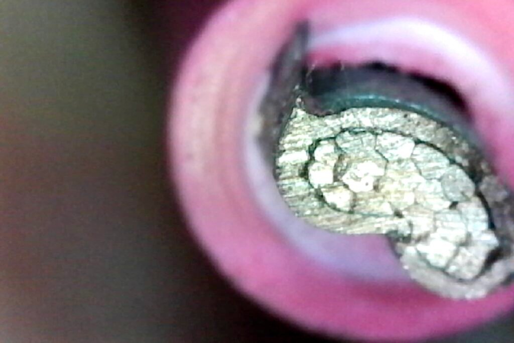
This is what a MC4 crimp looks like on 10AWG solar wire crimped in a 6mm die. It was a good crimp, but prepping it to take this shot screwed it up a little. I cut the body of the crimp off, then ground it flat. Sanded it with fine sandpaper and then etched it with muriatic acid. The grinding loosened the crimp on the right side slightly. But you can plainly see this isn’t just a mechanical connection, there isn’t a single round wire left. The wire in the center is almost a single conductor. This is what cold welding means. You can’t do this with pliers, or the funky crimper you use on butt connectors.
“Gas-tight” is exactly what you wind up with — no path for oxygen, moisture (or solder–seriously, don’t) to reach the interface means no oxide regrowth, no rising contact resistance, no thermal runaway.
So lets move on the the rest of making great connections as long as you SWEAR to get the proper crimping tool and learn to use it right. We’re going to show you that too.
The Tool Is Most of the Job
Nobody wants to hear this–you’re almost certainly been using the wrong tools, the wrong way. The technique is fairly easy. Devote some time to practice and ruin a few connectors and you’ve got it. The tool are a bit expensive, but absolutely necessary, the best one are crazy expensive, but there is no technique that rescues a really bad tool. Fortunately some of the bargain die-type crimpers are quite effective–you simply have to be a bit more careful in how you use them. The very best tools are nearly foolproof but I don’t see how an amateur or a DIYer would benefit enough to spend 800 bucks for one, no matter how good they are. Not when you can get an acceptable one that simply requires a bit more practice and care for $35.
A crimper that can cold-weld has three things going for it.
A die that closes to a controlled dimension. Not some crap four function tools that just dents the barrel and varies crimping pressure according to how hard you can squeeze —what you want is a specific final cross-section, every time, set by the tool and not by your grip. That’s why the good crimps ratchet. The ratchet is there to keep you from releasing the handles before the die is fully closed. Anything you can open mid-stroke will eventually produce a half-crimp. The springiness you feel is what sets the pressure–about 20 pounds. You can’t do more and you should never use the little trigger to release the ratchet and do less.
A die geometry that makes metal flow sideways. A hex die squeezes a round barrel into a hexagon, and most of that shape change is copper moving laterally past copper. A four-indent die (the MIL-DTL-22520 pattern) drives four punches inward at 90° to each other and folds the strands into a rosette. A B-crimp (most common for MC4) rolls the open barrel ears down and under so they curl into the strand bundle and then squashes the entire barrel into 1/4 the original volume. All three are doing the same thing — forcing plastic flow across the interfaces. A crappy automotive crimper with single nub pressing a dent into one side of a barrel is not doing that. It’s making a dent. Toss that in the trash
A locator that holds the contact at the right depth. This is one feature of premium toolsthat make them almost worth the price. The crimp has to land on the barrel, not on the transition to the pin and not off the end. Stäubli sells locators (the PV-LOC series) for exactly this, and better generic crimpers have a positioning nest molded in. If your tool lets the contact float, you’re eyeballing a dimension that the tool could control. That’s OK, but you need to be extra careful and check the location of every crimp.
Crimp tools for amphenol-type multi-pin connectors have a step that looks like a locating step, but that’s used because the tool crimps two sets of ears, one onto the bare wire and one on the insulator to provide strain relief. These are tricky to use, but they do a fine job if you spend a little time (and a few destroyed pins and sleeves) learning to use them
The tools I actually use
Stäubli’s own. The PV-CZM-63100 handles MC4 barrel crimp contacts across 14 through 8 AWG and is TÜV and UL certified. The 64100 is the combination kit that does both open and closed contacts. These are the tools the listing assumes you used, and Stäubli’s UL-relevant pliers stamp a witness mark into the crimp so an inspector can tell. If you are doing permitted work, or work someone else will inspect, this is the answer and the rest of this section is academic. But be prepared for sticker shock. Big time sticker shock. totally worth it if you’re a pro and someone is going to inspect your work. I love great tools. Some day I’ll probably buy one of these. Hey, I finally bought a Festool sander and now my dozens of other sanders are rotting in a drawer. But, wow.
There’s also the PV-CZM-BS at around $187, covering 2.5/4/6 mm². Note carefully: Stäubli themselves describe it as being for occasional field assembly of IEC-certified connectors, not UL certified. It makes a good crimp. It does not make a listed crimp. Know which one you need. And if you think 190 bucks is prohibitive, don’t look at the PV-CZM-63100
Good generic ratcheting hex-die crimpers. The 40–80 buck tools with interchangeable 2.5/4/6 mm² hex dies. Plenty of them make a legitimately gas-tight crimp. The catch is that you don’t know which ones until you check, and nobody really calibrates them. So you’ll need to check yourself, and return the ones that don’t work well. Here’s how: make three crimps, pull-test one to destruction, cross-section another, and use the third as your reference sample. Twenty minutes of work buys you confidence in a tool you’ll use for decades. If the cross-section looks like the photo above — no round wires left, strand boundaries mostly gone — you’re in business. You can apply the same process to the cheaper die crimpers (about 15-30 bucks) that have three dies in a row. Just make sure you have the dies you need. There are decent ones that have 6,4 and 2.5. Generally the 6 is closest to the inside and works well, the 4 and 2.5 not so much. So I have another set that does 4/2.5/1 and it works well for 4. I bought one of the better ones with interchangeable dies, and I like how precisely it works, but I’ve misplaced the 6. And now you know why we can’t have good things.
Die-type crimpers for heat-shrink butt and ring terminals. These exist and they’re good. They close a proper die on the barrel and cold weld the connection. If you’re going to use butt connectors — and there are places where you legitimately should — this is how. I have a hydraulic hand crimper that is supposed to cover 10AWG to 00. I tried to use it today with a 00 push on connector–doesn’t fit. There’s no way of knowing how thick the barrel might be so if you need to crimp 00 cable you probably want to buy one that has dies for 0000. But boy does that little hand crimper make some gorgeous butt splices.
The tools to throw in the bin
The stamped-steel “universal” crimper. You know the one. Blue and red and yellow color-coded jaws, a nub on one side, usually a bolt cutter and a screw shear built into the same handle. That nub was designed for thin-wall uninsulated brass terminals where the barrel is a rolled sleeve and all the tool has to do is dimple it enough to grip–they sucked for that too. It’s a connection on the way to failure. On a solid barrel contact it puts a dent in one wall and leaves the other 270° of circumference untouched. There is no lateral flow, no oxide fracture, and no gas-tight zone. It grips. It conducts, at first. It fails in year three when the un-welded copper inside has quietly oxidized and the contact resistance has climbed enough to make heat, which drives more oxidation, which makes more heat. That’s thermal runaway, and it’s most of the reason MC4s have the reputation they have. Never, ever use on one an MC4 connector–or any other connector if you care how long it lasts.
Pliers, vise-grips, channel locks, the side of a hammer. I’ve seen all four. No. And any “crimper” that also strips wire and cuts screws. A tool that does four jobs does none of them remotely well.
Stripping Wire Without Wrecking It
Rule one: the strip length equals the barrel length. Not a number off a chart, not “about half an inch.” Hold the actual contact you’re about to use alongside the wire, mark the insulation at the mouth of the barrel, and strip to the mark. Different manufacturers use different barrel depths in the same nominal size and the chart doesn’t know which one you bought.
Too short and you crimp partially — the die closes on air at the end, gets a little warm at max load and over time the heat cycles make the crimp get loose. Too long and you have bare copper hanging out past the barrel inside the housing, which can be a creepage-distance problem and, in a wet connector, a corrosion problem. If you’re using solar wire with a thicker than normal insulator that might be a mostly OK hack. If the plastic housing has a step the insulation won’t fit into you might not get the contact to click into place without a little extra wire length. If it doesn’t click, your plug might not fully engage the female contact. Extending the bare wire the depth of the step fixes that–sort of. Not perfect, but I can live with that as long as the cap seals tight.
Rule two: zero nicked strands. A nicked strand isn’t just a small loss of copper. It’s a stress riser sitting at the exact point where the wire flexes most — right at the mouth of the barrel, where a stiff crimped section meets flexible wire. Every thermal cycle and every wind gust works that spot. The nicked strand breaks first, the load shifts to its neighbors, and you get a cascade that ends with a hot joint and, eventually, an open circuit and the unwarranted conclusion that MC4 connectors suck.
So: a proper stripper. Self-adjusting type (the Knipex 12 series and its relatives), Stäubli’s PV-AZM if you want the matched tool, or a good gauge-hole stripper used in the right hole. Not a knife. Not the little notch in the side of your dikes. I use an adjustable insulation cutter intended for taking the cover off RJ45 cable. It makes a perfect flat end and never nicks if you adjust it properly. Look at the cut end under magnification when you’re dialing in the tool you use. This is a good use for a cheap USB microscope; you’ll see a scored strand at 60× that’s invisible at arm’s length. If you know you’re nicking wire you can make adjustments and then use the tool with confidence. The goal of all this testing and inspecting is to get the way you use tools down pat, so you don’t have to inspect every part to have confidence in the work you’re doing.
Things not to do to the stripped end:
Don’t twist it. Twisting works against the die. You want the strands to flow into each other under pressure, and a helix resists that — it wants to unwind rather than compress. Leave the lay the manufacturer put in it. It’s a small thing, but don’t just automatically twist the wire tighter.
Don’t tin it. Solder in a crimp is a rigid inclusion that prevents copper-to-copper flow and creates the stiff transition that cracks the wire. If the manufacturer tinned the copper strands individually, that’s fine. Copper corrodes quickly in air and makes a hard oxide surface. Tinning protects fine stranded copper and is a soft coating that doesn’t prevent cold welding. It’s radically different from turning the strands into a single blob of solder
NEVER trim strands to make it fit. If you have to cut strands to get the wire in, you have the wrong contact or the wrong wire. Stop and get the right part.
The right Die for common solar guages
Wire
Cross-section
Contact / die
14 AWG
2.08 mm²
2.5 mm²
12 AWG
3.31 mm²
4 mm²
10 AWG
5.26 mm²
6 mm²
8 AWG
8.37 mm²
10 mm²
Ten gauge is 5.26 mm², so it takes a 6 mm² contact and a 6 mm² die. It does not take a 4 mm² anything, no matter how much you’d like it to, and running 10 AWG in a 4 mm² die will crack the barrel. Going the other way — 12 AWG in a 6 mm² die — leaves the barrel under-compressed and there’s no cold weld at all. The die has to match the contact, and the contact has to match the wire.
Making the Crimp
Set the contact in the locator or the die nest. Ratchet down one click so it’s held but not deformed. If your tool has no locator, seat the barrel so the die lands on its center — not on the shoulder, not off the end. Sometime a gentle finger squeeze on the ears makes it easier to get the contact into the tool. The ears go into the part of the die that shapes the barrel–the side with a nib in the center that makes the profile look like a B.
Insert the wire until it stops. It should bottom against the internal shoulder. On open-barrel contacts you can see the strand ends past the crimp zone; on closed barrels, most have an inspection hole — look through it, you should see copper filling the window.
Squeeze to the release. All the way. The ratchet lets go when the die reaches its dimension; if it hasn’t let go, you’re not done. Don’t back out and re-squeeze — that’s a double crimp and it work-hardens the barrel. Not the end of the world, but a work-hardened barrel is more likely to crack.
Inspect it. Every one, takes three seconds:
Bell mouth — a slight flare at the insulation end of the barrel. Its presence means the die stopped where it should have. That little bell that looks like a mistake is lovely and means your wire won’t get stress cracks if it flexes
No stray strands anywhere outside the barrel.
No cracks in the barrel wall. Cracks mean the die was too small or the barrel was over-compressed.
Symmetric indents. A hex crimp should be a hexagon, not a lopsided pentagon. Lopsided means the contact wasn’t seated in the die. A B die should have both ears neatly folded into the center
Witness mark, if your tool stamps one.
Pull it. Grab the wire, grab the contact, and give it a solid tug — not a delicate test, a real pull. It should not move. Anything that moves at all, cut it off and start over. Once per session, sacrifice one to a scale (more on that below).
Seat it in the housing. Push the contact in until it clicks — you should hear it and feel it. Then pull on the wire. The retention tang has to be engaged; a contact that backs out under load inside a sealed housing is an arc fault waiting for a windy day.
Tighten the gland. Two spanners, one on each half, so you’re twisting the nut against the body and not torquing the whole assembly. Stäubli’s PV-MS set is the plastic version, PV-MS-PLS the metal one; the generic equivalents are fine here since they’re not touching the electrical path.
One more gland note that costs people systems: the compression seal is sized for a range of wire outside diameters. Put 12 AWG wire through a connector body designed for 10 AWG and the gland will never seal, no matter how hard you crank it. Water gets in, sits against a crimp you worked hard to make gas-tight, and corrodes it from the outside in. Match the connector body to the actual wire OD, not just the conductor size — and note that PV wire OD varies between manufacturers for the same gauge. The 10AWG solar wire I’m using is 7.63 mm in diameter–most 10AWG is a little over 6MM. The thick insulation is nice, it can handle a little nick or some rubbing and still meet voltage specs. But there are a LOT of MC4 connectors that have a stepped hole that fits 6.5 mm and below. I’m almost done with my two 500 foot reels. I’ll be happy to see the last of it. There are three common connectors I can use, and about 50 I can’t, though I can if I use the “little bit of exposed wire” hack to make up for not fitting in the step. Yeah, not perfect. I feel like a schmuck when I do it.
Where MC4-Type Connectors Come From, and What You Get
The name first, because it matters for what follows. MC4 is Stäubli’s product. MC stands for Multi-Contact, the company Stäubli acquired; the 4 is the 4 mm contact diameter. Everything else on the market is an MC4-compatible connector, which is a marketing claim, not a certification.
Stäubli original MC4 and MC4-Evo 2. The real thing. Silver-plated copper contacts, the tightest tolerances in the category, IEC 62852 and UL 6703. The limits are price and availability, and that’s it. If you’re building something you want to forget about for twenty-five years, buy these. (Evo 2 is the newer housing with a revised locking scheme — check Stäubli’s current documentation on mating Evo 2 to original MC4 before you mix them in one string, rather than assuming. But the documentation I looked at said they were compatible.). These connectors rock. Make them up properly and they just look and feel right. I tested the conductivity–it’s basically the same as the same length of wire.
Amphenol H4 / Helios H4. Genuinely good connectors, properly listed, made by a company that knows what it’s doing. They will physically plug into an MC4. Do not do that. More below.
Whatever came on your panels. Usually a house-branded generic from one of a handful of Chinese OEMs. Quality ranges from fine to alarming. The important thing is that this is the connector you’re stuck mating to, which constrains everything downstream.
Distributor house brands. Signature Solar, Current Connected, and the rest sell connectors under their own labels, generally sourced from one OEM at a time. Upside: cheap, sold in matched male/female pairs, available in the quantity you actually need, and the distributor has some reputational skin in the game. Downside: the OEM behind the label can change between lots, and many are IEC-certified without a UL listing. For off-grid and behind-the-meter work where you’re not pulling a permit, these are a reasonable buy. Just buy the whole job’s worth in one order.
Amazon and eBay bulk lots. Some are the same OEM parts the distributors sell, at a better price. Some are counterfeits with laser-etched Stäubli marks. You cannot tell from the listing photos, and the failure mode isn’t day one — it’s year three, in the rain. If you go this route, cross-section one and pull-test another before you install a hundred.
Screw-clamp and “tool-less” MC4s. The ones where you strip the wire, poke it into a cone, and tighten a set screw or a compression nut. These make a mechanical connection only. No plastic flow, no oxide fracture, no cold weld, no gas-tight interface — every failure mechanism this article exists to prevent, sold as a feature. They have exactly one legitimate use: getting a system back up in the field at dusk when you don’t have the tool. Replace it properly the next day. They truly suck. Every test I applied to these they failed miserably. A gentle tug rips the wire out of the connector.
The cross-mating problem. Note: This is NOT a technicality
Two connectors that click together are not necessarily compatible. Contact geometry, spring temper, plating chemistry, and tolerance all differ between manufacturers. Mate a Brand A male to a Brand B female and you can get reduced contact force, dissimilar-metal contact, or a housing that latches without the contacts fully engaging. Stäubli’s position is blunt: cross-mating causes “cracks, leakage and increase [in] contact resistance,” and the damage is usually undetectable at commissioning. No one has tested your ad hoc mixture. No one knows how long it will work–including you.
The standards agree:
IEC 62852 (the product standard) requires that male and female connectors be of the same type from the same manufacturer.
IEC 62548 (installation) says the same thing.
UL 6703 listings are granted to a mated pair, tested together. A Brand A male mated to a Brand B female is an untested combination and therefore an unlisted one, regardless of what each half is listed for individually.
NEC 690.33(C) requires mating connectors to be listed and identified for the purpose. As of the 2020 cycle, a cross-brand pair can comply only if both manufacturers explicitly document that specific intermateability. In practice, almost none do.
Field inspectors report finding mismatched connections in roughly a quarter of the systems they look at. It is one of the most common causes of PV connector fires, and it’s entirely avoidable: same brand, both halves, whole string, and buy enough at once that you don’t finish the job with a different lot.
Read that line one more time: One of the most common causes of PV connector fires
Testing the Connection
You made a crimp. Is it good? This took me a while to work out, because the obvious answer–check with an ohmmeter that has a low resistance setting–is wrong.
Your continuity beeper is lying
Set your multimeter to ohms and measure across a crimp. It reads 0.2 Ω, which is probably the resistance of your test leads. Set it to continuity and it beeps. It will also beep through a crimp made with pliers, a crimp with three strands actually connected, and a crimp that’s going to start a fire.
The numbers explain why. A good MC4 crimp plus its mated contact is a fraction of a milliohm — Stäubli publishes sub-milliohm figures for the mated pair. Your handheld DMM has 0.1 Ω resolution on its lowest ohms range and around 0.2 Ω of lead resistance. You’re trying to weigh a grain of sand on a bathroom scale, while standing on it.
You cannot measure a crimp with an ohmmeter. Push current through it instead and measure the voltage drop across it.
The millivolt drop test
This is the real test, it’s the one industry uses, and you can do it with the meter you already own.
The principle. R = V/I. Force a known current through the joint and measure the voltage across it. At useful currents the voltages land in a range your DMM measures accurately with variation for poor contact that is meaningful.
Why this works when the ohms range doesn’t: the current comes from an external supply through heavy leads, and your meter probes carry essentially no current. Lead resistance and probe contact resistance don’t enter the measurement. That’s a essentially a four-wire bridge measurement, done with your cheap DMM
The rig:
Bench supply in constant-current mode at 20 A, or a battery with a resistive load in series to set the current.
Sample wired in series with the source.
Confirm the actual current with a clamp meter or the supply’s readout — the math is only as good as this number.
Fuse it. Twenty amps into a short is not fun.
DMM on the 200 mV range.
The procedure:
Place both probes on the wire, roughly 10 mm outside each end of the crimp barrel. Same spacing every single time — mark the wire if you have to. Inconsistent probe spacing is the main source of error in this test.
Record the millivolts.
Now measure the identical probe spacing on an unbroken piece of the same wire. That’s your baseline: the drop the copper alone contributes.
Subtract. What’s left is the joint.
What to expect at 20 A:
Unbroken 10 AWG copper is about 3.3 mΩ per meter. A 20 mm span is roughly 0.066 mΩ — about 1.3 mV. Nearly nothing, which is the point.
A good crimp adds a few tenths of a milliohm at most. Total reading in the low single-digit millivolts.
A bad crimp at 5 mΩ reads 100 mV. Easy to read.
The pass criterion: the joint should add no more than the drop of an equivalent length of the same conductor. If your crimp reads meaningfully worse than an inch of the wire it’s attached to, it’s not a cold weld — it’s junk.
Run this on a properly-crimped sample, a nub-pliers sample, and a deliberately under-inserted sample. Three numbers, one obvious conclusion.
Confirming it with heat
P = I²R, so a bad joint doesn’t just measure worse — it makes heat. At 20 A, a 0.3 mΩ joint dissipates 0.12 W and stays cool. A 5 mΩ joint dissipates 2 watts inside something the size of a pencil eraser, and gets warm. You can do the math, or just see the heat.
The critical experimental control: wire the good sample and the bad sample in series. Then the current through both is absolutely, undeniably identical by definition, and nobody can argue you fed them different loads.
Three ways to read the temperature, in order of what I’d actually recommend:
Thermocouple — best value. A K-type bead thermocouple is a few dollars, and a great many DMMs have a K-type input built in. Tape one to each barrel with a wrap of electrical tape, run the current for five minutes to reach steady state, and read the difference. Direct contact means no emissivity problem and no spot-size problem. Two cheap meters you probably already have, two thermocouples (probably stuffed in the case the meter came in), two numbers on screen simultaneously — Nice, simple, clean, undeniable
An IR spot thermometer — usable, with care. Again, you probably already have one–I have three left over from years of racing cars. Unfortunately this will mislead you if you point it at bare copper. Two reasons:
Emissivity. An IR gun infers temperature from radiated energy, and how much a surface radiates depends on what it is. Black plastic sits around 0.95 and reads accurately. Bright copper is down around 0.05 — it radiates almost nothing, and reflects its surroundings instead. A 90 °C copper barrel can read near room temperature. The fix: put a strip of matte black electrical tape or a dab of flat black paint on both samples, at the same spot, and aim at that. Now both surfaces have the same known, high emissivity and the comparison is valid.
Spot size. These have a distance-to-spot ratio, often 8:1 or 12:1. At 12:1 and six inches away, you’re averaging everything inside a half-inch circle — which is bigger than the barrel you’re trying to measure. Get within two or three inches, and make the tape target large enough to fill the spot.
Do those two things and a spot gun gives you a defensible number. Skip them and your result is wrong by 60 °C.
A phone thermal camera. If you’re going to check your connections annually (you should), a $150–250 clip-on thermal imager pays for itself the first time you scan a combiner box or a service panel. The image of one connector glowing and the others dark communicates instantly what three paragraphs of millivolts cannot. Same emissivity caveat applies: tape both targets.
The pull test
Not a conductivity test, but it’s the acceptance test the specs actually mandate and it catches the same underlying failure. This is ugly, you just spent time and money making the best crimps you can. Now you clamp one end in a vise, attach a luggage or some other pull scale, pull steadily until it breaks and note the peak. The failure mode matters more than the number. A good crimp fails by breaking the wire outside the barrel, or by shearing strands. A bad one lets the wire slide cleanly out of the barrel with the strands intact and shiny. Clean pull-out means the cold weld never happened — there was nothing but friction holding it. In either care that connector is toast. But if it passed Kudos, you’re doing it right, we’re done here. If it didn’t, assume that every crimp you ever made is shit and you need to redo them all.
The aerospace tables (the SAE AS7928 family) give minimum tensile values by gauge, in the neighborhood of 50 lbf for 14 AWG, 70 for 12, and 90 for 10. Look them up against the current spec before you rely on them — I’m quoting from memory and these tables get revised.
And the ultimate test for the truly geeky
Thermal cycling. Make one good crimp and one nub-pliers crimp, measure both with the millivolt method, then cycle them — fifty on/off load cycles, or a few days shuttling between the shop bench and the freezer. Measure again.
The mechanical-only joint drifts upward. The cold-welded one doesn’t. Oh, and you’re nuts. I’m not gonna do that, but if you do, let me know how it turns out.
The TL;DR Version
Ratcheting die crimper, correct die for the contact, correct contact for the wire. No nub pliers, ever.
Strip to the barrel length, measured against the actual part. No nicked strands, no twisting, no tinning, no trimming.
Squeeze to the ratchet release. Inspect for bell mouth, stray strands, cracks, symmetry.
Pull-test every one by hand. Sacrifice one to a scale per session.
Click the contact into the housing, tug it, then two spanners on the gland.
Same brand both halves, whole string, one lot.
Test with millivolt drop under load, not with the continuity beeper.
Do that and MC4s stop being the most reviled connector in modern use, and go back to being what they actually are — a well-engineered part that most people install poorly with the wrong tool.
I’ve been telling people for years that changing tires is all about technique, not equipment, and you can change tires easily with just two small aluminum tire irons, and good tire lube. A bead holder is handy but not critical. I’m not wrong for smaller bikes, like dual sport and small-ish adventure bikes, or for vintage bikes with narrower rims than are common these days. But yesterday I changed the rear tire on my Ducati Desert-X, and it was a struggle. The stock rear tire is a Pirelli Scorpion Rally STR 150/70/18. My technique for “breaking” the bead is to slather on tire lube diluted with water and work around the rim with a tire iron, pushing the bead down a bit and letting the tire lube penetrate. After two or three revolutions around the tire the bead can be levered down into the dropcenter easily. But the Ducati has cross spoke, tubeless rims, and there’s no edge on the rim to lever against. So I needed to use my old tire mounting stand which has a simple bead breaker built in. I had to struggle with the bead for about 15 minutes to get it to push into the drop center. The other side went quicker, but was still a struggle. Getting the wheel out of the old tire is usually very easy if you have good tire lube–I generally just pull the wheel out by hand. But the sidewalls were so stiff that I had to use tire irons to get the rim out. About 30 minutes of struggling.
Mounting the new tire–a Dunlop Trailmax Mission–was quite a battle, the tire has even stiffer sidewalls than the stock Pirelli and the edges of the bead have a soft lip extension that might just be extraneous flash from the molding process, but might be intentional. It grabbed the rim and made it more difficult to lever the tire on. I was tempted to trim it off, but after I looked at it carefully it seemed too regular to be just mold flash. So I left it and just lubed it a bit more. I had to use long steel tire irons to make any progress. I lubed the beads with undiluted tire lube which made the tire and wheel quite slippery. It took me 20 minutes to get one side into the drop center, and then another 30 minutes to finish mounting the tire. The bead stop was a lifesaver, even though it won’t hook onto the spokes because the cross-spoke means the spokes are at a shallower angle, it still keeps the bead from slipping back off the rim, and kept the edge pointed towards the drop center. All in, it was more than an hour of struggling at something that usually takes 15 minutes and I had to use irons that I don’t usually carry. It’s a tubeless tire, I wouldn’t expect to have to dismount it on a ride to fix a flat, but I’m going to have to revisit my toolkit to prepare for the unlikely eventuality that I might have to do something grim by the side of the road. I doubt I could make progress with my dinky aluminum irons that I find so useful for narrower wheels and tires.
So yes, to anyone I might have mislead or offended with my blithe comment that it’s all just technique–sorry about that. I’ve changed hundreds of motorcycle tires over my riding life, both as a pro mechanic and as a committed amateur with a LOT of bikes and friends that need help with their bikes. I’ve never struggled this much (that I remember). One shop I worked at had a tire machine–I used it several times but it damaged a nice Akront rim so I never used it again. But if I did big wheels and wide tires very often, I might be tempted to try a tire machine or at least built a better stand to do the work.
I saw a video recently of a BDR trip where a guy rode 60 miles round trip to the nearest town with a wheel strapped to his back to get his buddy’s tire fixed because they couldn’t repair it themselves. I know that seems crazy, but it could happen to you if you don’t learn to work on your own tires before you venture out. Trail side in the middle of nowhere is not the place to learn you don’t have the tools or skills to fix your own tire problems.
In this video we’ll cover four things that will help you replace a tire or repair any kind of flat without drama. First is the fundamental things you need to know to work on tires. The second section covers tools, both in your shop and those you carry to avoid being stranded. Third is the parts and spares you’ll want both in your shop and on your bike. Number 4 is how you use your tools and fundamental understanding to change tires or fix flats without struggling. And then I’ll show you one bonus tip to give you pro-level results no matter whether you’re working in your shop or in the middle of a trackless desert.
#1 The first thing you need to understand is how the design of wheel rims enable you to lever a stiff, un-stretchable bead onto a rim that is larger in circumference than the bead. Every wheel rim (other than two piece rims, which are not typically used for motorcycles) has a valley in the center of the rim called the drop center. The bead of the tire fits tightly on the step next to the rim and is reinforced either with steel wire or some super-strong fiber. The circumference of the drop center is, of course, quite a bit smaller than the circumference of the bead. You cannot stretch a bead onto the rim unless the remainder of the bead is in the drop center which reduces the effective circumference of the wheel to about the same size as the bead. If the tire bead is well lubed you can lever the bead on with even short, wimpy tire irons–if and ONLY if you keep the rest of the bead in the drop center. When you see someone struggle to get a tire back onto a rim it’s simply because they didn’t lube the bead well enough or are not keeping all of the bead except for the section they are levering in the drop center. That’s all you need to do, you don’t need an expensive tire machine. Just a bit of understanding and some tire lube.
That brings us to #2–Tools. I have an absurdly large collection of tire tools collected over the 60+ years I’ve been wrenching on bikes, but the tire irons I carry on my bike are cheap, light, and they’re aluminum so they won’t ding most rims. They have box wrenches on the ends. One has both a 10 and 13 mm box, and the other has a 32mm box with inserts that reduce it to 29 and 27 mm so you can remove most axle nuts or adjust the chain. I tested them to 60 foot/lbs of torque with no significant damage.
Some people swear by tire irons that include a bead breaker. First of all, if you apply good tire lube and just work your way around the rim with the tire iron, the lube will seep into the bead area and just a bit more levering will usually break the bead. In stubborn cases I prefer to use my feet or a motorcycle kickstand for breaking beads. I also carry a bead buddy, which both keeps the bead from chasing around the rim when you remount the tire, and also keeps the bead in the valley at the center of the rim. And finally I always carry tire lube that lets the bead slip into place and also helps seat the bead once you have the tire on the bike. Some people recommend silicone spray lube, but a persistent lubricant is a terrible idea. Even days later if your tire is not at full pressure it can let your wheel spin inside the tire, turning an air down or slow leak into an un-repairable ripped out valve stem. I carry a small ziplock bag with a shop rag that has a healthy dab of NoMar tire lube. Add water and squish it around and you have a pro-quality tire lube. A small tub of No-Mar will last your entire life. You can also use the solution like soapy water to locate a pinhole leak.
I also carry a combination battery-powered compressor/jump starter/power bank/flashlight. It’s a bit bulky though it fits nicely in my tank bag or in the side pocket of my Mosko Moto R10 bags. Not only is it a great tire inflation tool that accurately reads your tire pressure and shuts off automatically when it reaches a pressure you set, but I’ve used it to jumpstart a 6.7 liter diesel engine as well as my husky 701. I leave it plugged into my USB outlet so it’s always at 100 percent when I stop for the night. The LED flashlight could probably run for a week or two–I’ve used it as a camp light for hours without seeing any change in charge level. You’d think I’d be satisfied with that, but I also carry three CO2 cartridges and a tire inflation adapter. Because shit breaks. I’ve never used the CO2 cartridges, but they are tiny, and I hate being stranded by random failures. And I carry a prop stand which can be used in conjunction with the kickstand to hold either the front or rear tire off the ground. It’s much lighter and more compact than a center stand.
Topic #3 is spares and repair kits. Two of my dirt bikes are tubeless, two have tubed tires. If I had a choice they all would be tubeless. The most common flat tire by a huge margin is a puncture in the tread of the rear tire. The ability to repair that with just a plug that takes moments to install is too good to ignore. Plus tubeless cross-spoke wheels with straight spokes that have the heads in the rim and nipples in the hub like this VMX aftermarket wheel from my KTM 390 ADV are much stronger, stay truer, and are easier to repair than traditional spoke wheels. The only benefit of traditional tubed spoked wheels is that they are cheaper.
But hey, Mr. Tubeless tires, what if you get a sidewall rip that can’t be plugged? Well, first I’d stare in amazement at a flat that is rarer than winning the lottery. And then I’d install the spare tube I always carry. Which I also carry on my tubed bikes–because when a rear tire goes flat you’re likely to tear the valve stem out unless you have good rimlocks. You can’t patch a torn out valve stem. I carry just a front tube which will work for both the front and rear tire. No, I don’t buy heavy duty tubes, which I consider pure marketing bullshit. they don’t offer any benefit and make it much harder to install or repair tubed tires. And I never use slime or any other magic liquid that’s supposed to plug flats. You can’t repair a tube with slime in it. it makes a mess and doesn’t work. If I was riding hard enduros or rallies, I’d use mousses, but they are brutal on pavement or higher speed dirt sections.
I carry a tube patch kit always, because even though I’ve changed or fixed hundreds of motorcycle tires, I’m still capable of pinching the tube with a tire iron. If you do pinch the tube you’ll need a patch kit when you stop swearing and kicking things. My tube patch kit includes three CO2 cartridges and the tire filling adapter which I mentioned in section 2. While it might be belt and suspenders since I carry a compressor, these suspenders pack tiny.
For my bikes with tubeless tires I carry both the typical sticky string plug kit (because it’s tiny) and a larger, more complex mushroom plug kit, because it makes a permanent repair. Again, belt and suspenders, but I hate getting stranded. The mushroom plug kit is amazing because you can install the plugs without dismounting the tire. I put a tiny dab of tire lube on the plug, and then the installation tool compresses the mushroom through this little tube and extends the plug a graduated distance into the tire carcass. When you pull the installation tool out it seats the plug and you can cut it off flush. I have a Conti TKC70 tire on my KTM 390 ADV that has more than 10,000 miles with a mushroom plug installed. I’d show it to you but I can’t spot it from the outside–its that well integrated into the tire.
Topic # 4 is a demo of how to fix a flat or change a tire. I’ve seen far more people do it wrong than do it right. First you need to break the bead, meaning you need to unstick the tire bead from the edge of the rim. Tubeless tires present a little extra challenge because there’s an added rim on the inside of the bead that keeps the bead in contact with the outer rim–one good reason that simply sealing spoke nipples with tape and goo doesn’t make a good tubeless spoke wheel (besides the simple unreliability of a sealing hack). My favorite method of breaking beads in the field is to just use tire lube and work tire irons in as far as they will go and wiggle them–the lube penetrates deeper until most of the bead is lubricated. It becomes increasingly easy to work the tire irons in, and finally just pressing down on a deeply inserted tire iron will pop the bead away from the rim. My second favorite way is to use body weight–put the wheel on the ground with your folded jacket under it to protect the bearings, and step on the tire. If that doesn’t work I generally take the sprocket off to keep from damaging it and I use the weight of the bike, concentrated on the kickstand to force the tire away from the rim. It’s a bit clumsy, but it works. If that’s not enough then you sit on the bike with the kickstand on the tire, which is even clumsier unless you enlist a buddy to help you, but in a pinch, that will pop even the most stubborn bead.
Now lube the bead and rim copiously with more tire lube solution. Push the bead down into the drop center in the middle of the rim, and either secure it with a bead buddy or use your knee to keep it there while you lever the bead over the rim on the side opposite your knee or bead buddy. Work your way around the tire a bit at a time until you have the bead completely off the rim. If at any time it takes excessive force to lever out the bead, check to be sure the bead on the opposite side of the tire is still in the drop center and push as much of the bead into the drop center as you can. Having the bead in the drop center effectively reduces the diameter of the rim, making it much easier to get the tire off.
Repair or replace the tube, add a little air to make it easier to get it completely into the tire and feed the valve stem through the hole in the rim. Start putting the tire back on by levering the tire onto the rim close to the valve stem. If you have a bead buddy, insert it to keep the bead in place, or just leave one of your tire irons in place and keep it pressed down to stop the bead from slipping off. Once you have about half the tire on pay attention to keeping the segment already installed deep into the drop center. If it starts getting hard to lever on the bead, check to be sure the already installed bead is well into the drop center. If it isn’t, levering on the tire will get harder and harder.
Once you have the tire on you need to seat the bead. That simply means inflating the tire until the bead pops up against the rim. If you’re using a good tire lube that will happen well before you get to typical inflation pressure. Usually, a well lubed motorcycle tire will seat before you reach five pounds of pressure. There is usually a line on the sidewall that should be an equal distance from the rim around the tire. Finally, adjust the tire pressure to the correct value. You shouldn’t need to, but you can over-inflate the tire about 50% to get the bead to seat. If you can’t get it to pop into place with whatever you have for inflation tools it doesn’t mean you can’t ride the bike. It might thump a bit on pavement but the bead is likely to seat itself as you use it, especially if you’ve used enough tire lube.
Yeah, I know, “what oil should I use” is what bored or clueless folk post on any FaceBook motorcycle forum to see how many pointless comments they can get. Everyone has an opinion on what oil should be used, which is generally what they use, backed by nothing more authoritative than “I’ve been using this for XX years” . Here’s the thing–doing the same thing for a long time is more an indication that the poster has never considered or studied alternatives. It’s more a borderline admission of stubborn stupidity rather than a qualification.
I love to learn new things, I don’t consider long experience to be a qualification. As I’ve said many times, I’ve been working on bikes longer than most of you have been alive, and I do stupid shit every day. But I do look for expert information, so I’m pleased to offer this email I recently got from “Toxic Terry” who I’ve received great information from previously about chain lube. This is sort of a continuation of that discussion and I hope to take this a bit further this spring, with a deep dive into general lubrication issues, as goofy as that sounds when I type it. Anyway, here’s the latest from Toxic Terry:
I am the fellow rider who sent you information concerning the potential use of DigiLube Ultra Film 1 for motorcycle chain maintenance. As a retired organic chemist, my interest in lubricants has grown exponentially over the past years as the evolution of synthetic lubricants has become a reality. In the case of DigiLube, the base oil is conventional, but the additive package is synthetic in that the specific lubricant to provide ‘dry lubrication properties’ is a compound that effectively bonds lubricant molecules to the oxide coating present on all common metal surfaces exposed to the environment which contains oxygen. Following application, the base oil [solvent not lubricant] evaporates leaving behind a chemically bonded molecular lubricant that will not wash off with solvents or water and is stable under extreme pressures and moderately high temperatures. Considering the exposure of motorcycle chains to particulates, mud, water, salt, sand and other contaminants, the fundamental property of a bonded dry lubricant is expected to maximize lubrication without retaining solids which can act as abrasives during operation. This is the fundamental property that makes DigiLube an optimum product for motorcycle chain maintenance. Other non-bonded lubricants like silicones and heavy oils/greases all suffer the problem of retaining solids and that is their characteristic weakness if chain longevity is desired.
Let’s consider automotive lubricants next. Motor oils are grouped into five classes which range from naturally occurring oils [Dyno juice = Class I] to Class V lubricants that are synthesized by reacting small organic molecules to form high molecular weight compounds. To be honest, as a professional organic chemist, the advent of commercially available Class V motor oils should eliminate consideration of using any other lubricant in one’s motorcycle. For that reason, I will not go into all the pros and cons of the Class I to IV lubricants as they are ‘antiquated’ relics compared to the superior properties exhibited by the one of the two kinds of Class V synthetics.
Class V oils are of two basic types: polyethers and polyesters. Polyethers are not typically used in conventional internal combustion engines as they are ‘sensitive’ to water and in some cases, even soluble in water. Polyesters are the cream of the crop from a chemist’s perspective when it comes to physical properties that are important to provide superior lubrication under extreme conditions of heat and shear. It is for this reason that I recommend using Class V polyester oils in motorcycle engines where the internal components are operating at high speeds, high temperatures with a moderately low volume of lubricant present in the recirculating system.
As mentioned, diol-based Class V synthetic oils can be synthesized in two formats depending on the initiator molecule. The most common is a diol [a molecule that has an alcohol group attached to each end of a hydrocarbon chain] that reacts with various dicarboxylic fatty acids to form long chain, linear polyesters. These are definitely better than any of the lower class lubricants in terms of their physical properties. However, there is a better molecular structure, one that produces spherical [actually star-shaped is more accurate] molecules which begins with a pentaerythritol initiator. These polyesters, being spherical in structure, provide the ultimate lubricant properties because of their resistance to breakdown under shear. Linear molecules tend to break which produces two chains of shorter length which leads to loss of viscosity and increased volatility. Spherical molecules can suffer a chain break on one of the arms but such degradation has a much reduced influence on viscosity loss because the fundamental molecular weight is reduced by a much lower fraction. While both types of polyesters have similar lubrication properties, those with spherical molecular structure offer significantly longer useful lifetimes from a chemical perspective. Because the manufacturers of synthetic motor oils consider their formulations to be proprietary, it is difficult to understand exactly what type of polyester you are purchasing. However, price per unit volume is often a clue. Lower priced Class V polyester oils are cheaper than the ‘high- end’ varieties that are composed of spherical molecules because of differences in the synthesis procedures employed. My personal understanding to date is the premium motorcycle oils [and automotive oils] from Amsoil are pentaerythritol-based lubricants which yield the spherical molecules I have described.
So, why are spherical polyester lubricants so effective compared to other motor oils? Pure hydrocarbons are designated non-polar while polyesters are polar. Chemistry teaches that “like dissolves like” which is incredibly important in an internal combustion engine. Combustion byproducts are partially oxidized hydrocarbons which range from carbonaceous solids to a vast variety of other polar substances. Pure hydrocarbon lubricants do not readily dissolve such polar by-products; hence the additives package of the oil must contain considerably higher concentrations of other chemicals to handle the lack of solubility issues. Such additives are not as resistant to degradation as the base oil and have a limited capacity which explains why cheaper oils have much shorter lifetime expectancies under operating conditions. While all motor oils, including Class V polyesters, have a substantial presence of additives to aid in preventing corrosion, adding lubricity, providing cold flow characteristics and viscosity modulation, the amount in the spherical molecular based polyesters is considerably less than all other such motor oils including the linear molecular based polyesters.
Polyesters are chemically very strong molecules compared to pure hydrocarbons and because polyesters are polar, they adhere strongly to metallic surfaces [compared to pure hydrocarbons] which is the primary reason they are such good lubricants. One notices this property when rebuilding an engine. It is somewhat difficult to remove the oil from parts as typical hydrocarbon solvents [paint thinner] do not readily dissolve it. In my experience, it takes acetone or methylene chloride to effectively remove it from a metal surface. Because polar polyesters dissolve most of the combustion by-products, the oil becomes dark and the internal metallic surfaces remain free of grunge that one encounters when using a pure hydrocarbon oil. The property of spherical molecular polyesters to reduce loss of viscosity caused by chain breakage provides significantly longer operational time between oil changes. Lower concentrations of additives to the base oil also leads to longer lifetimes as the base oil already possesses the necessary properties that the additives provide. Less additives means more base oil per unit volume, and it is the base oil that is the working fluid providing lubricity.
Bottom line: polyester lubricants have no competition when it comes to the chemical properties that are required for lubricating typical internal combustion engines. Those brands composed of spherical molecules are the best available option if ultimate performance as a lubricant is important. Amsoil, and perhaps some others, have such chemistry which is why I use them exclusively in all my motors.
OK, cool. So that’s what Toxic Terry says, and it sounds good to me, but what do I know? So I enlisted my friend Mr. Perplexity to do a little fact checking.
This is Deep Seek R1 (via Perplexity.AI), or rather here’s a link to my query and Deep Seek’s response. The link will open a local version of Perplexity for you. In the unlikely event you worry about opening your kimono to a Chinese AI the perplexity model is housed on Perplexity’s servers in the USA. Perplexity AI is owned by its founders, Aravind Srinivas, Denis Yarats, Johnny Ho, and Andy Konwinski, with a shit ton of outside money from Jeff Bezos and NVidia. I’m in the process of building my own Deep Seek server, just for the hell of it. https://www.perplexity.ai/search/please-analyze-the-following-a-_Zt57GG.SUKGUEnraaXjZg
This is the first, of (I hope) many posts from other experts, which was part of the original plan for Expert Amateur. I intended to solicit content from other experts on various topics. This came unsolicited on the Adventure Riders forum in the 390 ADV owners thread from a member with the unlikely avatar name “Toxic Terry”. I have a heavily modified KTM 390 ADV that I’ve occasionally posted about on the site. I’m publishing this unedited, which is how I intend to handle any other contributions from outside experts. I think the information here clearly meets the requirement of expertise, having a retired Analytical Scientist from Dow Chemical provide thoroughly tested information on chain lubricants is remarkable, and I’m pleased to present this.
Sir: I am a 77 year old retired Analytical Scientist from The Dow Chemical Company. I am not in your league for riding history, skills, mechanical expertise or most other ‘motorcycle’ stuff. However, I have been riding since 2002: 02 CRF-450, 04 KTM 300, 06 Husky TE-610, 09 Versys 650 [highly modified to become an adventure bike by Dan Djokovic [Indy Unlimited on this site] … and now, a 24 KTM 390 Adventure with tubed spoked wheels and as such have gone through many iterations of chain maintenance. Over the course of the past couple weeks, I have been reading my way through the 800+ pages of the 390 thread and have taken many notes on ‘stuff’ you have attempted to educate the general ridership herein. I appreciate the time and effort you have expended to tell some of your stories and, more importantly, to educate folks on the ‘technical’ background behind many aspects of motorcycles.
Recently, there were posts regarding ‘chain maintenance’ and as usual, there were many different “opinions” regarding how to maintain a given chain, regardless of its particular build. I read what you had to say and in most respects, are in agreement. But, I do want to provide you with some long-term experimental data I have accumulated over the years trying to figure out what is the best means to maximize chain longevity. Being a laboratory scientist, I have employed the Scientific Method to investigate all sorts of ‘situations’ that involve chemicals and how they interact with physical systems such as conveyors and chains. As such, motorcycle chains are right up my alley as an experimentalist, even when the experiments are conducted in a garage rather than a laboratory.
Rather than go through the many iterations of chain cleaning and maintenance routines I have explored over the years, I will simply cut to the chase and give you the information I believe to be ‘best practices’. I am not putting this stuff out to the public on this thread because I know how ‘touchy’ folks can get when it comes to engine oil and cleaning chains. LoL … maybe, if you find my information reasonable, perhaps you can ‘advise’ the rest of the inmates … your word will go a lot farther than from a noob like me.
First, and perhaps foremost, there are no chain lubrication materials in spray cans or otherwise that lengthen a chain’s lifespan. All of these products, some of which actually advertise that their stuff ‘won’t fling off’, result in the deposition of high molecular weight organic hydrocarbons on the surface of the chain. These materials become the perfect abrasive when mixed with inorganic particulates [dirt]. Such abrasives slowly wear on the pin seals and eventually lead to the pins beginning to wear which is the reason the chain grows in length. I frown on the word ‘stretch’ in this case because chains to not stretch. Another way of looking at this phenomenon is to examine a chain that his been operated with a Scott Oiler device. Applying a continuous stream of hydrocarbon oils that are not highly volatile [evaporate easily under normal operating conditions] keeps the chain wet and therefore a better matrix upon which dirt particles can adhere. My riding buddy, Dan Djokovic, had one of these on his BMW F800GS … we installed new chains at the same time [mine on my Husky TE-610 with no oiler], then we ran the bikes until the chains began to lengthen [first data point], then until the chain needed to be replaced. The Scott Oiler chain had to be adjusted after only ~2500 miles and thereafter about every 3 to 4 K miles. Interestingly, my Husky chain, which was treated as described below, didn’t need adjustment for over 8000 miles. The Scott Oiler chain needed to be changed after approximately 10K miles while my Husky chain got almost 15K miles before biting the dust. Dan removed the oiler after this experiment and his chains achieved the same type of longevity as mine using the same treatment procedures.
Bottom line: motorcycle chains are best cleaned and lubricated with a material that is composed of a volatile hydrocarbon which serves as the solvent for specialized ‘dry lubricants’. The molecular weight of the hydrocarbon solvent is sufficiently large so as to not be a ‘super good solvent’ like paint thinner, but low enough to evaporate under ambient, or above, conditions. The ‘dry lubricants’ are chemicals that form a strong chemical bond with metal oxides present on the surface of chains exposed to the environment. These dry lubricants essentially form a monomolecular layer of ‘lubricity’ enhancing chemicals that can withstand extreme pressures, will not wash off with either aqueous or non-aqueous solvents, do not attract and retain particulate matter and do not harm any of the polymers used in O- or X-ring pin seals. The downside of such ‘dry lubricants’ is that the monomolecular layer of lubricity will wear off under normal use and therefore needs to be refurbished regularly. In other words, after each day’s ride, reapplication via soaking the chain and wiping dry with a towel, is required and is best achieved while the chain is still warm if possible. This process takes me approximately 2 minutes to accomplish.
Here’s the magic elixir for chain cleaning, lubrication and general maintenance:
I have been using this stuff for about 15 years or so … it is absolutely amazing shit to say the least. The only real problem relative to its application to motorcycle chains is the fact that a 5 gallon pail is the smallest commercially available unit. Dan and I have purchased 15 gallons over our years of riding together [unfortunately he passed away a couple years ago] … we repackaged the stuff into gallons and sold our bulk supply to other riders to recoup some of the expense. A gallon will last the average rider at least a year, maybe two, depending how often he rides and how many other things he finds to ‘clean & lubricate’. Just for the record, I use this stuff to lube almost every moving part of my motorcycles: pegs, levers, etc. Works really well on garage door bearings too … much better than that messy lithium grease often recommended.
There are a couple more points that need be mentioned regarding chain maintenance that are in my opinion important factors in longevity. The first one involves installing a brand new chain. As received, chains are coated with a low molecular weight paraffin hydrocarbon [wax] as a storage preservative. Failure to remove this wax can dramatically shorten the life span of a given chain. I have seen many folks just wipe the chain with a rag, or a solvent-soaked rag, then install it. The preservative wax is bad news in that it melts under operating conditions, can accumulate in the gap surrounding the pin seals, then collect dirt particles and begin the abrasion process. To avoid such a result, removing the wax is imperative, however, submerging the chain in any hydrocarbon-based solvent is not recommended as solvents like paint thinner can penetrate the pin seal and dilute the captured grease in the link slot leading to premature failure. I have found that placing a new chain in a plastic dish pan, adding about 2 ozs of Digilube 1 to the pan, sloshing the chain around in the solvent, then scrubbing the outside surfaces of each link with a soft bristled tooth brush. Remove the chain from the pan, thoroughly wipe with a clean towel, then lay the chain on a bench and using the toothbrush, dipped in residual Digilube that was in the dish pan, brush each inner surface of the links and finally, wipe chain with the clean towel. Flip the chain over on the bench, repeat the process again from the other side. Upon a final wipe with a clean towel, looking at the inner surfaces of the chain should reveal no visible wax remaining. I sometimes need a Q-tip to augment the toothbrush, but I am OCD as hell and a fanatic about operating principles. This process takes me about 30 minutes to accomplish.
The second important point involves routine daily ‘relubrication’ after each ride. This process is simple. Lift the real wheel so you can spin the chain, drip Digilube 1 from a plastic dispensing bottle on the chain as it passes over the rear sprocket. The chain needs to receive a thorough soaking with Digilube to the point that it is dripping off the chain. If any macro particulate deposits are observed, use a brush to remove them [usually not necessary from my experience, but if one just ran through a mud hole prior to ending the ride, then definitely a possibility], and finally wiping the chain with a rag to remove excess lubricant and any residual particulates.
Not sure if many folks know about Digilube 1, but from my perspective as someone who is fascinated by minutiae, it is ‘magic’ in bottle. Sorry if this catches you off guard, but hopefully something you find interesting to add to your repertoire of motorcycling mayhem.
Regards:
Terry Nestrick
[Toxic Terry is my handle from ages ago when folks knew me from my reputation as an ultra-trace analyst specializing in the measurement of dioxins and other noxious chemicals commonly found in the environment and commercial products]