
The MC4 connector is probably the most reviled electrical connector in modern use–and it’s not the connector’s fault. We’re going to cover more than just the MC4, and the basics here apply to almost everything you want to connect in power electrics/electronics. I’ve read hundred of posts in solar forums, and on facebook, about making up connections. They all share one thing in common, they aren’t even close to being right. Many are so far off I can’t even call them wrong. Flat out stupid is more like it. Yeah, I know, them’s fightin’ words.
Eighty Years of Cold Welding–Why Crimping Beat Solder: Ask a room of electricians why they crimp instead of solder, and you’ll get a confident answer from almost everyone — and about four different explanations. Solder is brittle. Solder wicks. Flux corrodes (even rosin–that’s how it works!). Heat damages the insulation. All of these are true, and none of them is the actual reason.
The real reason is that a properly executed crimp isn’t a mechanical grip at all. It’s closer to a weld. And like a good weld–it’s permanent. The degradation curves pictured below don’t apply.
This isn’t a modern discovery or a manufacturer’s marketing angle. Solderless compression connectors go back to the 1920s, when utilities building out aluminum transmission line ran into a conductor that simply doesn’t solder well. Aircraft-Marine Products — the company that became AMP — built its entire wartime business on crimped terminals for aircraft wiring, because a crimp survives vibration, needs no flux, and can be made correctly in seconds by someone who was working in a different trade last month. By the early 1950s the practice was written into military specification. By the the Apollo program came along, NASA’s reliability engineering had reached the same verdict for wire-to-terminal joints: crimp, don’t solder. Commercial and international standards followed through the 1970s and 80s.
It’s not a matter of opinion or something you can choose to do differently and still have good results. It’s the proven standard–as long as you do it the right way. So when you crimp a lug onto a battery cable, you’re not taking the quick option. You’re using the method that aerospace settled on eight decades ago, after testing the alternatives and rejecting them all.
What makes it work is worth understanding in detail — because once you know what’s happening inside that barrel, the rules stop being arbitrary. Crimp height, die geometry, tool calibration, pull-out testing: every one of them exists to protect a specific physical mechanism. Here’s what that mechanism actually is, and where the popular “cold weld” description gets it slightly wrong.
Let’s look at the base problem. A bad connection gets worse over time. When I try to explain this mechanism to people in online forums, their skepticism is obvious. “So, my connector has been good for years and then it suddenly goes bad and burns up–is that what you’re telling me?” Yes, that is exactly what happens, and the entire process has been well-known for eight decades. I asked Claude to build me an interactive explanation I could show here. You can play with the graph to see what is happening at each point. This is how your connections burn up. And I hope for you that the only thing that burns is the connector.
The Loose Connection Curve
A high-resistance joint does not necessarily fail immediately. It can hold a noisy plateau for years while clamp force bleeds off and oxide grows, then it crosses a threshold where I²R heating and Arrhenius oxide kinetics close a positive-feedback loop — and the remaining life collapses from years to hours–and burns in the process. This is the shape of that trajectory, and where the two field tests that catch it actually sit on it.
Contact resistance of a bolted lug, 100 A service
Log scale — the plateau and the runaway differ by four decades. Both joints were torqued to spec on day one; the marginal joint simply had a little less clamp force and a little more oxygen.
Plateau
yr 0 – 8.5 · ~130 µΩResistance wanders but does not trend. Oxide growth is parabolic and self-limiting; conduction carries the heat away faster than it is made. Nothing in this record predicts the knee — which is why absolute resistance is a poor field metric and trend-against-a-reference-joint is a good one.
Knee
yr 8.5 – 11 · 0.2 → 20 mΩClamp force has fallen far enough that constriction resistance rises, interface temperature rises with it, and oxidation rate — exponential in temperature — rises again. dR/dt is now a function of R. Intermittents and arcing noise appear here, months before anything looks wrong.
Runaway
final hours · >100 mΩThe interface sustains ~1000 °C in a millimetre-scale volume while the conductor a few centimetres away is merely warm. It can hold there for hours — long enough to ignite the enclosure — without ever drawing enough current to trip the breaker protecting the circuit.
What starts it: preload decay
Stress relaxation, roughly logarithmic in time, ratcheted by thermal cycling.
The knee, expanded
Interface temperature over the last six hours of Phase III.
Across a whole panel
Weibull hazard, β = 2.4 — a wear-out population, not a random one.
Why the knee is vertical
Four terms, one loop. Below threshold the loop gain is under unity and the joint is stable for decades; above it, nothing stops the climb but the copper melting.
Where to catch it
Both tests read the joint against a reference, not against an absolute. Thresholds below follow the commonly-cited NETA acceptance-testing tables; confirm against the current edition for spec work.
| Reading | Verdict | Action |
|---|---|---|
| Thermography — ΔT vs. reference joint | ||
| 1 – 3 °C | △ Possible deficiency | Log it, re-shoot next survey |
| 4 – 15 °C | ◆ Probable deficiency | Repair at next outage |
| > 15 °C | ■ Major discrepancy | Repair immediately |
| Millivolt drop — across the joint at rated current | ||
| ≤ 1.5× reference | ● Within band | No action |
| > 1.5× reference | ◆ Investigate | Break, clean, re-torque to spec |
| 50 mV @ 100 A | ◆ = 500 µΩ | The dashed line on the chart above |
Crimp it, with the right tool, and leave the solder for electronics
Yes, I know, there are lots of opinions about this. Fortunately, the professional opinions including aerospace and military wiring specs (MIL-DTL-22520 and others) all agree: Crimp-only for nearly all applications. Crimp plus solder is simply ridiculous. If you do a proper crimp with the right tool there is no way for solder to enter the cold-welded, gas-tight connection. Solder wicks up into the strands and creates a stiff-to-flexible transition point that work-hardens and cracks. A crimp keeps the whole thing ductile.
You might think cold welding is just some techy-sounding marketing. But it’s real. With the right tools the pressure in the crimp die absolutely welds the connection. And the need for the right tools and the right dies isn’t restricted to just MC4 connectors. Any multi-pin amphenol-style connector requires the same care, and so do the butt connectors that some people (I’m struggling very hard to not say “fools”, and apparently loosing the battle) claim are superior to MC4s (they most assuredly are NOT). The typical cheap pliers with a penetrating nub that damages the insulation and dents the barrel does not provide even some minimal welding. There are die-type crimpers for shrink tube butt- and terminal-connectors that do the same cold welding job and but unfortunately damage the shrink tube as much or more than the useless nub-style crimper. I haven’t found a way to avoid that, I’m not sure there is one. my solution is to slip a shrink tube over the damaged area. The benefit of the integrated shrink tube is to provide waterproofing and stress relief at the barrel of the conductor. Here’s what happens when you use a true cold-welding crimper on a connection:
- Oxide gets fractured. Copper and the barrel both carry an oxide skin that’s an insulator. As the die closes, the metal flows laterally and the brittle oxide layer cracks and gets scrubbed aside, exposing virgin metal.
- The metal goes plastic. Crimp pressures run high enough to exceed the yield strength of both the strands and the barrel. Strands deform against each other and against the barrel wall, filling voids. Cross-section it and you can barely find the boundaries between individual strands — they’ve flowed into a near-solid mass.
- Clean metal meets clean metal under pressure. Once two oxide-free metal surfaces are pressed together within atomic distances, metallic bonding occurs spontaneously — the electron sea doesn’t care which side of the old interface an atom came from. That’s the same mechanism as cold welding in vacuum (why bare metal parts in space can seize together), just localized to the die–which experiences MUCH higher pressures than you’d expect–tons per square inch, because the area inside the die is less than a square millimeter.
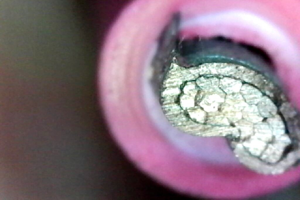
This is what a MC4 crimp looks like on 10AWG solar wire crimped in a 6mm die. It was a good crimp, but prepping it to take this shot screwed it up a little. I cut the body of the crimp off, then ground it flat. Sanded it with fine sandpaper and then etched it with muriatic acid. The grinding loosened the crimp on the right side slightly. But you can plainly see this isn’t just a mechanical connection, there isn’t a single round wire left. The wire in the center is almost a single conductor. This is what cold welding means. You can’t do this with pliers, or the funky crimper you use on butt connectors.
“Gas-tight” is exactly what you wind up with — no path for oxygen, moisture (or solder–seriously, don’t) to reach the interface means no oxide regrowth, no rising contact resistance, no thermal runaway.
So lets move on the the rest of making great connections as long as you SWEAR to get the proper crimping tool and learn to use it right. We’re going to show you that too.
The Tool Is Most of the Job
Nobody wants to hear this–you’re almost certainly been using the wrong tools, the wrong way. The technique is fairly easy. Devote some time to practice and ruin a few connectors and you’ve got it. The tool are a bit expensive, but absolutely necessary, the best one are crazy expensive, but there is no technique that rescues a really bad tool. Fortunately some of the bargain die-type crimpers are quite effective–you simply have to be a bit more careful in how you use them. The very best tools are nearly foolproof but I don’t see how an amateur or a DIYer would benefit enough to spend 800 bucks for one, no matter how good they are. Not when you can get an acceptable one that simply requires a bit more practice and care for $35.
A crimper that can cold-weld has three things going for it.
A die that closes to a controlled dimension. Not some crap four function tools that just dents the barrel and varies crimping pressure according to how hard you can squeeze —what you want is a specific final cross-section, every time, set by the tool and not by your grip. That’s why the good crimps ratchet. The ratchet is there to keep you from releasing the handles before the die is fully closed. Anything you can open mid-stroke will eventually produce a half-crimp. The springiness you feel is what sets the pressure–about 20 pounds. You can’t do more and you should never use the little trigger to release the ratchet and do less.
A die geometry that makes metal flow sideways. A hex die squeezes a round barrel into a hexagon, and most of that shape change is copper moving laterally past copper. A four-indent die (the MIL-DTL-22520 pattern) drives four punches inward at 90° to each other and folds the strands into a rosette. A B-crimp (most common for MC4) rolls the open barrel ears down and under so they curl into the strand bundle and then squashes the entire barrel into 1/4 the original volume. All three are doing the same thing — forcing plastic flow across the interfaces. A crappy automotive crimper with single nub pressing a dent into one side of a barrel is not doing that. It’s making a dent. Toss that in the trash
A locator that holds the contact at the right depth. This is one feature of premium toolsthat make them almost worth the price. The crimp has to land on the barrel, not on the transition to the pin and not off the end. Stäubli sells locators (the PV-LOC series) for exactly this, and better generic crimpers have a positioning nest molded in. If your tool lets the contact float, you’re eyeballing a dimension that the tool could control. That’s OK, but you need to be extra careful and check the location of every crimp.
Crimp tools for amphenol-type multi-pin connectors have a step that looks like a locating step, but that’s used because the tool crimps two sets of ears, one onto the bare wire and one on the insulator to provide strain relief. These are tricky to use, but they do a fine job if you spend a little time (and a few destroyed pins and sleeves) learning to use them
The tools I actually use
Stäubli’s own. The PV-CZM-63100 handles MC4 barrel crimp contacts across 14 through 8 AWG and is TÜV and UL certified. The 64100 is the combination kit that does both open and closed contacts. These are the tools the listing assumes you used, and Stäubli’s UL-relevant pliers stamp a witness mark into the crimp so an inspector can tell. If you are doing permitted work, or work someone else will inspect, this is the answer and the rest of this section is academic. But be prepared for sticker shock. Big time sticker shock. totally worth it if you’re a pro and someone is going to inspect your work. I love great tools. Some day I’ll probably buy one of these. Hey, I finally bought a Festool sander and now my dozens of other sanders are rotting in a drawer. But, wow.
There’s also the PV-CZM-BS at around $187, covering 2.5/4/6 mm². Note carefully: Stäubli themselves describe it as being for occasional field assembly of IEC-certified connectors, not UL certified. It makes a good crimp. It does not make a listed crimp. Know which one you need. And if you think 190 bucks is prohibitive, don’t look at the PV-CZM-63100
Good generic ratcheting hex-die crimpers. The 40–80 buck tools with interchangeable 2.5/4/6 mm² hex dies. Plenty of them make a legitimately gas-tight crimp. The catch is that you don’t know which ones until you check, and nobody really calibrates them. So you’ll need to check yourself, and return the ones that don’t work well. Here’s how: make three crimps, pull-test one to destruction, cross-section another, and use the third as your reference sample. Twenty minutes of work buys you confidence in a tool you’ll use for decades. If the cross-section looks like the photo above — no round wires left, strand boundaries mostly gone — you’re in business. You can apply the same process to the cheaper die crimpers (about 15-30 bucks) that have three dies in a row. Just make sure you have the dies you need. There are decent ones that have 6,4 and 2.5. Generally the 6 is closest to the inside and works well, the 4 and 2.5 not so much. So I have another set that does 4/2.5/1 and it works well for 4. I bought one of the better ones with interchangeable dies, and I like how precisely it works, but I’ve misplaced the 6. And now you know why we can’t have good things.
Die-type crimpers for heat-shrink butt and ring terminals. These exist and they’re good. They close a proper die on the barrel and cold weld the connection. If you’re going to use butt connectors — and there are places where you legitimately should — this is how. I have a hydraulic hand crimper that is supposed to cover 10AWG to 00. I tried to use it today with a 00 push on connector–doesn’t fit. There’s no way of knowing how thick the barrel might be so if you need to crimp 00 cable you probably want to buy one that has dies for 0000. But boy does that little hand crimper make some gorgeous butt splices.
The tools to throw in the bin
The stamped-steel “universal” crimper. You know the one. Blue and red and yellow color-coded jaws, a nub on one side, usually a bolt cutter and a screw shear built into the same handle. That nub was designed for thin-wall uninsulated brass terminals where the barrel is a rolled sleeve and all the tool has to do is dimple it enough to grip–they sucked for that too. It’s a connection on the way to failure. On a solid barrel contact it puts a dent in one wall and leaves the other 270° of circumference untouched. There is no lateral flow, no oxide fracture, and no gas-tight zone. It grips. It conducts, at first. It fails in year three when the un-welded copper inside has quietly oxidized and the contact resistance has climbed enough to make heat, which drives more oxidation, which makes more heat. That’s thermal runaway, and it’s most of the reason MC4s have the reputation they have. Never, ever use on one an MC4 connector–or any other connector if you care how long it lasts.
Pliers, vise-grips, channel locks, the side of a hammer. I’ve seen all four. No. And any “crimper” that also strips wire and cuts screws. A tool that does four jobs does none of them remotely well.
Stripping Wire Without Wrecking It
Rule one: the strip length equals the barrel length. Not a number off a chart, not “about half an inch.” Hold the actual contact you’re about to use alongside the wire, mark the insulation at the mouth of the barrel, and strip to the mark. Different manufacturers use different barrel depths in the same nominal size and the chart doesn’t know which one you bought.
Too short and you crimp partially — the die closes on air at the end, gets a little warm at max load and over time the heat cycles make the crimp get loose. Too long and you have bare copper hanging out past the barrel inside the housing, which can be a creepage-distance problem and, in a wet connector, a corrosion problem. If you’re using solar wire with a thicker than normal insulator that might be a mostly OK hack. If the plastic housing has a step the insulation won’t fit into you might not get the contact to click into place without a little extra wire length. If it doesn’t click, your plug might not fully engage the female contact. Extending the bare wire the depth of the step fixes that–sort of. Not perfect, but I can live with that as long as the cap seals tight.
Rule two: zero nicked strands. A nicked strand isn’t just a small loss of copper. It’s a stress riser sitting at the exact point where the wire flexes most — right at the mouth of the barrel, where a stiff crimped section meets flexible wire. Every thermal cycle and every wind gust works that spot. The nicked strand breaks first, the load shifts to its neighbors, and you get a cascade that ends with a hot joint and, eventually, an open circuit and the unwarranted conclusion that MC4 connectors suck.
So: a proper stripper. Self-adjusting type (the Knipex 12 series and its relatives), Stäubli’s PV-AZM if you want the matched tool, or a good gauge-hole stripper used in the right hole. Not a knife. Not the little notch in the side of your dikes. I use an adjustable insulation cutter intended for taking the cover off RJ45 cable. It makes a perfect flat end and never nicks if you adjust it properly. Look at the cut end under magnification when you’re dialing in the tool you use. This is a good use for a cheap USB microscope; you’ll see a scored strand at 60× that’s invisible at arm’s length. If you know you’re nicking wire you can make adjustments and then use the tool with confidence. The goal of all this testing and inspecting is to get the way you use tools down pat, so you don’t have to inspect every part to have confidence in the work you’re doing.
Things not to do to the stripped end:
- Don’t twist it. Twisting works against the die. You want the strands to flow into each other under pressure, and a helix resists that — it wants to unwind rather than compress. Leave the lay the manufacturer put in it. It’s a small thing, but don’t just automatically twist the wire tighter.
- Don’t tin it. Solder in a crimp is a rigid inclusion that prevents copper-to-copper flow and creates the stiff transition that cracks the wire. If the manufacturer tinned the copper strands individually, that’s fine. Copper corrodes quickly in air and makes a hard oxide surface. Tinning protects fine stranded copper and is a soft coating that doesn’t prevent cold welding. It’s radically different from turning the strands into a single blob of solder
- NEVER trim strands to make it fit. If you have to cut strands to get the wire in, you have the wrong contact or the wrong wire. Stop and get the right part.
The right Die for common solar guages
| Wire | Cross-section | Contact / die |
|---|---|---|
| 14 AWG | 2.08 mm² | 2.5 mm² |
| 12 AWG | 3.31 mm² | 4 mm² |
| 10 AWG | 5.26 mm² | 6 mm² |
| 8 AWG | 8.37 mm² | 10 mm² |
Ten gauge is 5.26 mm², so it takes a 6 mm² contact and a 6 mm² die. It does not take a 4 mm² anything, no matter how much you’d like it to, and running 10 AWG in a 4 mm² die will crack the barrel. Going the other way — 12 AWG in a 6 mm² die — leaves the barrel under-compressed and there’s no cold weld at all. The die has to match the contact, and the contact has to match the wire.
Making the Crimp
- Set the contact in the locator or the die nest. Ratchet down one click so it’s held but not deformed. If your tool has no locator, seat the barrel so the die lands on its center — not on the shoulder, not off the end. Sometime a gentle finger squeeze on the ears makes it easier to get the contact into the tool. The ears go into the part of the die that shapes the barrel–the side with a nib in the center that makes the profile look like a B.
- Insert the wire until it stops. It should bottom against the internal shoulder. On open-barrel contacts you can see the strand ends past the crimp zone; on closed barrels, most have an inspection hole — look through it, you should see copper filling the window.
- Squeeze to the release. All the way. The ratchet lets go when the die reaches its dimension; if it hasn’t let go, you’re not done. Don’t back out and re-squeeze — that’s a double crimp and it work-hardens the barrel. Not the end of the world, but a work-hardened barrel is more likely to crack.
- Inspect it. Every one, takes three seconds:
- Bell mouth — a slight flare at the insulation end of the barrel. Its presence means the die stopped where it should have. That little bell that looks like a mistake is lovely and means your wire won’t get stress cracks if it flexes
- No stray strands anywhere outside the barrel.
- No cracks in the barrel wall. Cracks mean the die was too small or the barrel was over-compressed.
- Symmetric indents. A hex crimp should be a hexagon, not a lopsided pentagon. Lopsided means the contact wasn’t seated in the die. A B die should have both ears neatly folded into the center
- Witness mark, if your tool stamps one.
- Pull it. Grab the wire, grab the contact, and give it a solid tug — not a delicate test, a real pull. It should not move. Anything that moves at all, cut it off and start over. Once per session, sacrifice one to a scale (more on that below).
- Seat it in the housing. Push the contact in until it clicks — you should hear it and feel it. Then pull on the wire. The retention tang has to be engaged; a contact that backs out under load inside a sealed housing is an arc fault waiting for a windy day.
- Tighten the gland. Two spanners, one on each half, so you’re twisting the nut against the body and not torquing the whole assembly. Stäubli’s PV-MS set is the plastic version, PV-MS-PLS the metal one; the generic equivalents are fine here since they’re not touching the electrical path.
One more gland note that costs people systems: the compression seal is sized for a range of wire outside diameters. Put 12 AWG wire through a connector body designed for 10 AWG and the gland will never seal, no matter how hard you crank it. Water gets in, sits against a crimp you worked hard to make gas-tight, and corrodes it from the outside in. Match the connector body to the actual wire OD, not just the conductor size — and note that PV wire OD varies between manufacturers for the same gauge. The 10AWG solar wire I’m using is 7.63 mm in diameter–most 10AWG is a little over 6MM. The thick insulation is nice, it can handle a little nick or some rubbing and still meet voltage specs. But there are a LOT of MC4 connectors that have a stepped hole that fits 6.5 mm and below. I’m almost done with my two 500 foot reels. I’ll be happy to see the last of it. There are three common connectors I can use, and about 50 I can’t, though I can if I use the “little bit of exposed wire” hack to make up for not fitting in the step. Yeah, not perfect. I feel like a schmuck when I do it.
Where MC4-Type Connectors Come From, and What You Get
The name first, because it matters for what follows. MC4 is Stäubli’s product. MC stands for Multi-Contact, the company Stäubli acquired; the 4 is the 4 mm contact diameter. Everything else on the market is an MC4-compatible connector, which is a marketing claim, not a certification.
Stäubli original MC4 and MC4-Evo 2. The real thing. Silver-plated copper contacts, the tightest tolerances in the category, IEC 62852 and UL 6703. The limits are price and availability, and that’s it. If you’re building something you want to forget about for twenty-five years, buy these. (Evo 2 is the newer housing with a revised locking scheme — check Stäubli’s current documentation on mating Evo 2 to original MC4 before you mix them in one string, rather than assuming. But the documentation I looked at said they were compatible.). These connectors rock. Make them up properly and they just look and feel right. I tested the conductivity–it’s basically the same as the same length of wire.
Amphenol H4 / Helios H4. Genuinely good connectors, properly listed, made by a company that knows what it’s doing. They will physically plug into an MC4. Do not do that. More below.
Whatever came on your panels. Usually a house-branded generic from one of a handful of Chinese OEMs. Quality ranges from fine to alarming. The important thing is that this is the connector you’re stuck mating to, which constrains everything downstream.
Distributor house brands. Signature Solar, Current Connected, and the rest sell connectors under their own labels, generally sourced from one OEM at a time. Upside: cheap, sold in matched male/female pairs, available in the quantity you actually need, and the distributor has some reputational skin in the game. Downside: the OEM behind the label can change between lots, and many are IEC-certified without a UL listing. For off-grid and behind-the-meter work where you’re not pulling a permit, these are a reasonable buy. Just buy the whole job’s worth in one order.
Amazon and eBay bulk lots. Some are the same OEM parts the distributors sell, at a better price. Some are counterfeits with laser-etched Stäubli marks. You cannot tell from the listing photos, and the failure mode isn’t day one — it’s year three, in the rain. If you go this route, cross-section one and pull-test another before you install a hundred.
Screw-clamp and “tool-less” MC4s. The ones where you strip the wire, poke it into a cone, and tighten a set screw or a compression nut. These make a mechanical connection only. No plastic flow, no oxide fracture, no cold weld, no gas-tight interface — every failure mechanism this article exists to prevent, sold as a feature. They have exactly one legitimate use: getting a system back up in the field at dusk when you don’t have the tool. Replace it properly the next day. They truly suck. Every test I applied to these they failed miserably. A gentle tug rips the wire out of the connector.
The cross-mating problem. Note: This is NOT a technicality
Two connectors that click together are not necessarily compatible. Contact geometry, spring temper, plating chemistry, and tolerance all differ between manufacturers. Mate a Brand A male to a Brand B female and you can get reduced contact force, dissimilar-metal contact, or a housing that latches without the contacts fully engaging. Stäubli’s position is blunt: cross-mating causes “cracks, leakage and increase [in] contact resistance,” and the damage is usually undetectable at commissioning. No one has tested your ad hoc mixture. No one knows how long it will work–including you.
The standards agree:
- IEC 62852 (the product standard) requires that male and female connectors be of the same type from the same manufacturer.
- IEC 62548 (installation) says the same thing.
- UL 6703 listings are granted to a mated pair, tested together. A Brand A male mated to a Brand B female is an untested combination and therefore an unlisted one, regardless of what each half is listed for individually.
- NEC 690.33(C) requires mating connectors to be listed and identified for the purpose. As of the 2020 cycle, a cross-brand pair can comply only if both manufacturers explicitly document that specific intermateability. In practice, almost none do.
Field inspectors report finding mismatched connections in roughly a quarter of the systems they look at. It is one of the most common causes of PV connector fires, and it’s entirely avoidable: same brand, both halves, whole string, and buy enough at once that you don’t finish the job with a different lot.
Read that line one more time: One of the most common causes of PV connector fires
Testing the Connection
You made a crimp. Is it good? This took me a while to work out, because the obvious answer–check with an ohmmeter that has a low resistance setting–is wrong.
Your continuity beeper is lying
Set your multimeter to ohms and measure across a crimp. It reads 0.2 Ω, which is probably the resistance of your test leads. Set it to continuity and it beeps. It will also beep through a crimp made with pliers, a crimp with three strands actually connected, and a crimp that’s going to start a fire.
The numbers explain why. A good MC4 crimp plus its mated contact is a fraction of a milliohm — Stäubli publishes sub-milliohm figures for the mated pair. Your handheld DMM has 0.1 Ω resolution on its lowest ohms range and around 0.2 Ω of lead resistance. You’re trying to weigh a grain of sand on a bathroom scale, while standing on it.
You cannot measure a crimp with an ohmmeter. Push current through it instead and measure the voltage drop across it.
The millivolt drop test
This is the real test, it’s the one industry uses, and you can do it with the meter you already own.
The principle. R = V/I. Force a known current through the joint and measure the voltage across it. At useful currents the voltages land in a range your DMM measures accurately with variation for poor contact that is meaningful.
Why this works when the ohms range doesn’t: the current comes from an external supply through heavy leads, and your meter probes carry essentially no current. Lead resistance and probe contact resistance don’t enter the measurement. That’s a essentially a four-wire bridge measurement, done with your cheap DMM
The rig:
- Bench supply in constant-current mode at 20 A, or a battery with a resistive load in series to set the current.
- Sample wired in series with the source.
- Confirm the actual current with a clamp meter or the supply’s readout — the math is only as good as this number.
- Fuse it. Twenty amps into a short is not fun.
- DMM on the 200 mV range.
The procedure:
- Place both probes on the wire, roughly 10 mm outside each end of the crimp barrel. Same spacing every single time — mark the wire if you have to. Inconsistent probe spacing is the main source of error in this test.
- Record the millivolts.
- Now measure the identical probe spacing on an unbroken piece of the same wire. That’s your baseline: the drop the copper alone contributes.
- Subtract. What’s left is the joint.
What to expect at 20 A:
- Unbroken 10 AWG copper is about 3.3 mΩ per meter. A 20 mm span is roughly 0.066 mΩ — about 1.3 mV. Nearly nothing, which is the point.
- A good crimp adds a few tenths of a milliohm at most. Total reading in the low single-digit millivolts.
- A bad crimp at 5 mΩ reads 100 mV. Easy to read.
The pass criterion: the joint should add no more than the drop of an equivalent length of the same conductor. If your crimp reads meaningfully worse than an inch of the wire it’s attached to, it’s not a cold weld — it’s junk.
Run this on a properly-crimped sample, a nub-pliers sample, and a deliberately under-inserted sample. Three numbers, one obvious conclusion.
Confirming it with heat
P = I²R, so a bad joint doesn’t just measure worse — it makes heat. At 20 A, a 0.3 mΩ joint dissipates 0.12 W and stays cool. A 5 mΩ joint dissipates 2 watts inside something the size of a pencil eraser, and gets warm. You can do the math, or just see the heat.
The critical experimental control: wire the good sample and the bad sample in series. Then the current through both is absolutely, undeniably identical by definition, and nobody can argue you fed them different loads.
Three ways to read the temperature, in order of what I’d actually recommend:
Thermocouple — best value. A K-type bead thermocouple is a few dollars, and a great many DMMs have a K-type input built in. Tape one to each barrel with a wrap of electrical tape, run the current for five minutes to reach steady state, and read the difference. Direct contact means no emissivity problem and no spot-size problem. Two cheap meters you probably already have, two thermocouples (probably stuffed in the case the meter came in), two numbers on screen simultaneously — Nice, simple, clean, undeniable
An IR spot thermometer — usable, with care. Again, you probably already have one–I have three left over from years of racing cars. Unfortunately this will mislead you if you point it at bare copper. Two reasons:
- Emissivity. An IR gun infers temperature from radiated energy, and how much a surface radiates depends on what it is. Black plastic sits around 0.95 and reads accurately. Bright copper is down around 0.05 — it radiates almost nothing, and reflects its surroundings instead. A 90 °C copper barrel can read near room temperature. The fix: put a strip of matte black electrical tape or a dab of flat black paint on both samples, at the same spot, and aim at that. Now both surfaces have the same known, high emissivity and the comparison is valid.
- Spot size. These have a distance-to-spot ratio, often 8:1 or 12:1. At 12:1 and six inches away, you’re averaging everything inside a half-inch circle — which is bigger than the barrel you’re trying to measure. Get within two or three inches, and make the tape target large enough to fill the spot.
Do those two things and a spot gun gives you a defensible number. Skip them and your result is wrong by 60 °C.
A phone thermal camera. If you’re going to check your connections annually (you should), a $150–250 clip-on thermal imager pays for itself the first time you scan a combiner box or a service panel. The image of one connector glowing and the others dark communicates instantly what three paragraphs of millivolts cannot. Same emissivity caveat applies: tape both targets.
The pull test
Not a conductivity test, but it’s the acceptance test the specs actually mandate and it catches the same underlying failure. This is ugly, you just spent time and money making the best crimps you can. Now you clamp one end in a vise, attach a luggage or some other pull scale, pull steadily until it breaks and note the peak. The failure mode matters more than the number. A good crimp fails by breaking the wire outside the barrel, or by shearing strands. A bad one lets the wire slide cleanly out of the barrel with the strands intact and shiny. Clean pull-out means the cold weld never happened — there was nothing but friction holding it. In either care that connector is toast. But if it passed Kudos, you’re doing it right, we’re done here. If it didn’t, assume that every crimp you ever made is shit and you need to redo them all.
The aerospace tables (the SAE AS7928 family) give minimum tensile values by gauge, in the neighborhood of 50 lbf for 14 AWG, 70 for 12, and 90 for 10. Look them up against the current spec before you rely on them — I’m quoting from memory and these tables get revised.
And the ultimate test for the truly geeky
Thermal cycling. Make one good crimp and one nub-pliers crimp, measure both with the millivolt method, then cycle them — fifty on/off load cycles, or a few days shuttling between the shop bench and the freezer. Measure again.
The mechanical-only joint drifts upward. The cold-welded one doesn’t. Oh, and you’re nuts. I’m not gonna do that, but if you do, let me know how it turns out.
The TL;DR Version
- Ratcheting die crimper, correct die for the contact, correct contact for the wire. No nub pliers, ever.
- Strip to the barrel length, measured against the actual part. No nicked strands, no twisting, no tinning, no trimming.
- Squeeze to the ratchet release. Inspect for bell mouth, stray strands, cracks, symmetry.
- Pull-test every one by hand. Sacrifice one to a scale per session.
- Click the contact into the housing, tug it, then two spanners on the gland.
- Same brand both halves, whole string, one lot.
- Test with millivolt drop under load, not with the continuity beeper.
Do that and MC4s stop being the most reviled connector in modern use, and go back to being what they actually are — a well-engineered part that most people install poorly with the wrong tool.