A recent comment from Will Prowse about PV disconnect switches really turned a light on for me (pun intended). Especially since it contradicted some bad advice I’ve been giving people. He was saying, for lower current installations that a properly rated little polarized DC breaker makes a serviceable disconnect switch, as long as it’s ganged so you open both legs–positive and negative. Blew my mind until I thought about it some. I considered a breaker to be a bad choice because they aren’t really made to be used as switches. The contacts aren’t super heavy, they don’t open far enough to extinguish arcs, and the way the closing mechanism works it can be hard to tell if the contacts get welded together. They use various devices to blow the arc out, and if that fails, they burn up. And I don’t mean they get hot. I mean they melt and catch fire. But there is a way to use them as a disconnect. But ONLY as a disconnect.
There has been quite a bit of confusion in the comments for the YouTube video I made about the value of a DC breaker connected to PV panels for managing faults and over-current. The point of that video and this blog post is using DC breakers AS A SWITCH. I know this is confusing, but there are benefits in using a polarized DC breaker as a switch for a solar disconnect while NOT relying on them for managing fault current. Most high quality combiner boxes use appropriately rated line fuses for each series string and a polarized DC breaker purely as a disconnect switch for doing maintenance. Combiner boxes are frequently located remotely from the solar controllers and inverters that might need to be opened for service. Adding an additional disconnect switch at the equipment location is both a good practice, and is frequently required by local codes.
I need to credit the people who commented on the YouTube video version of this post, in particular a fellow named Matt, who commented as junkerzn7312. I’ve used their comments, and especially his to dig a little deeper into the subject, and even excerpted parts of his comment.
Why do we need a PV disconnect? Well, modern PV panels in a series string might be producing more than 500 volts at 10 or more amps as long as there’s sunshine. That’s enough to kill a horse instantly. If you get across that, hand to hand or hand to foot, you’re dead. Period. End of story. Shutting down your inverter does NOTHING to prevent that. If anything, it increases the voltage and the hazard. If you’re going to do any kind of work inside your inverter you need to ABSOLUTELY disconnect the PVs, the disconnect has to be reliable, and you need to check everything where you’re going to be working so you know there’s no significant voltage. If you don’t it can kill you. Perhaps worse, it can blind or injure you horribly. I can’t emphasize this enough. Don’t just shrug this off and say “Oh, I’ve been shocked before”. This isn’t that.
People used to working with older PV installations that produced less than 80 volts are often fairly casual about the hazard. You can stick your wet, sweaty hands on the terminals of a 12V battery and never feel a thing. Do that with wet hands on 48V battery and you’ll get a nasty shock. Above 80 volts you’re probably dead. Above 300 volts there’s no question. You’re irretrievably gone. Even if someone is standing by with a defibrillator your heart is probably cooked medium rare. Really. When I was a stupid kid I used to cook hot dogs in my bedroom by sticking nails wired to a wall plug into the ends. It’s quicker than a microwave. I’ve inexplicably made it to 77. Do NOT try this at home (and if you’re that crazy, don’t use galvanized nails).
DC disconnects of all types have two challenges. Challenge 1: A DC arc doesn’t extinguish on it’s own like AC will, because AC passes through 0 volts about 120 times a second for 60 cycle. Something has to happen to make a DC arc stop. Either the contacts need to get far enough apart, or something needs to intercede to blow out the arc. Getting the contacts far enough apart is a good solution, and that means several inches. That’s why big knife switches that look like they belong in Dr. Frankenstein’s lab are common in high power DC disconnects. At lower power rotary switches that move the contacts 180 degrees or more through a curving tunnel does the trick. A little lower still in power, and DC breakers that separate the contacts less but include internal structures or features that chop up the arc, cool it off and then shove the pieces apart can work.
Challenge 2: Contacts in a dc disconnect can weld shut as they close, especially if closing them connects the DC to an instantaneously heavy load, like inverters with big capacitors on the input. AC isn’t good at welding contacts but DC is great at it. With a knife or rotary switch the welded contacts can be forced apart or at least let you know by feel (for example, you can’t turn the switch). With a breaker the indication is more subtle, masked by the spring that does the actual closing. Interrupting both positive and negative reduces the possibility that one welded breaker will leave the system energized with potentially fatal voltage. The welding can also be mitigated with some bypass circuitry to momentarily reduce the current. Some DC breakers sold as PV disconnects have a version of this or some other mechanical way of dealing with welded contacts.
So how do disconnect switches, and DC breakers effectively disconnect series string PV panels? There are two methods–Brute force and trickery. Sounds like a Harry Potter premise. Disconnect switches can use both. Breakers need to rely on trickery. Let’s do breakers first.
DC breakers have to do two jobs–they need to trip on overcurrent and they need to disconnect when the breaker is opened. As with all breakers there is an arming step after the breaker is opened to re-latch the trip mechanism and then load up the spring. Some DC breakers re-arm the latch when they open since the strong spring has enough power to do so. Most AC breakers require the user pull the toggle full open and then close the breaker.
The contacts can’t really move very far apart given the space limitations, the bulk of the trip mechanism, and the linear movement of the contacts. How quickly the contacts move apart is important to extinguishing the arc. In a breaker the contacts are also only moved by a relatively light stored energy spring action–the toggle doesn’t bear directly on the moving contact but just arms the spring and sets the latch. Given these limitations, trickery is called for, and these take the form of arc chutes (structures that cool, chop, and stretch the arc), permanent magnets that steer the arc into the chute an elongate it, and sometimes magnetic blowout coils that use a magnetic field to deflect and elongate the arc.
Almost all DC breakers and some AC breakers have some form of arc chute, which are simply parallel insulated metal plates near the contacts. When the contacts are opened the arc is pushed by convection or by permanent magnets into the plates which chop the arc into smaller segments and cool the ionized gas. The small, cooler arc sections extinguish as the arc path lengthens and the ionized gas that conducts the arc cools below the plasma level.
DC breakers generally come in two flavors, polarized and unpolarized. Most unpolarized DC breakers are rated under 100VDC and these rely on opening the contact quickly and widely. There may be an ARC chute but there aren’t any magnets pushing the arc into the chute–just convection. Because they rely mostly on the gap, higher voltage unpolarized DC breakers tend to be big and expensive
Polarized DC breakers can operate with higher voltages and they can be relatively cheap and small. Since they use permanent magnets to direct the ARC away from the contacts and into the arc chute they don’t need a lot of space and the arc is extinguished quickly in the chute. But if the user connects a polarized DC breaker incorrectly it pushes the arc away from the arc chute and the arc persists. The plasma of a DC arc is more than 5,000°F. That’s enough to melt steel. The plastic case is on fire very quickly. And then everything gets a lot worse.
DC circuit breakers with dual permanent magnets can be designed to be non-polarized, but the mere presence of two magnets does not automatically make a breaker non-polarized. The key factor is how these magnets are arranged and how they interact with the arc during circuit interruption.
Dual Magnet Configurations
In non-polarized DC circuit breakers, dual permanent magnets are typically arranged with opposite poles facing each other on both sides of the arc extinguishing chamber. This configuration allows for effective arc management regardless of current direction.
Key aspects of this design include:
1. Balanced Magnetic Fields: The opposing magnets create balanced magnetic fields that can interact with the arc in either direction of current flow.
2. Bidirectional Arc Control: This arrangement allows the breaker to elongate and cool the arc effectively, regardless of current polarity.
3. Flexible Installation: Non-polarized breakers can be connected in any orientation, eliminating concerns about matching circuit and breaker polarities
Polarized DC breakers are suitable only when the current flow is going in one direction. So they make perfect sense as a PV Disconnect. They should NEVER be used in any situation where the current can flow in both directions, such as a battery. They can be applied bi-directionally as a 4-pole breaker when wired so each of the two DC legs pass through two breakers with reverse polarity. In this way regardless of the direction of current flow the arc will be pushed into the arc chute in one of the two breakers. The potentially destructive arc in the breaker with the wrong polarity will be extinguished when the breaker with the proper polarity opens the circuit. This has the benefit of permitting smaller, less expensive breakers to be used, but requires four pole breakers, which are bulky and can be almost as expensive as non-polarized breakers. The breakers with the wrong polarity may suffer some damage but the arcs are extinguished quickly enough to minimize it so this may be a useful hack.
Polarized DC breakers are dangerous because so many people connect them incorrectly. The labeling is confusing to inexperienced users, the “+” and “-” labels indicate current direction, NOT voltage polarity. In addition to appropriate fusing, DIY solar projects should always use unpolarized DC breakers for all low-voltage DC wiring–generally everything that connects to the battery bus. Polarized DC breakers should only be used in a few special cases such as solar PV disconnects where high voltages are present where they offer a distinct advantage over similarly rated disconnect switches: DC breakers (polarized or unpolarized) are obviously designed to operate safely under load. DC disconnect switches frequently are NOT designed to operate under load.
A DC breaker in a Solar DC disconnect should be in the current path AFTER any paralleling occurs. You should never use polarized DC breakers as solar DC disconnects on a per-string basis if multiple strings may be paralleled, because the current can flow in either direction during a short or failure situation. Solar DC disconnects should be rated for at least 1000VDC (or higher). Typical solar combiner boxes have per-string fuses and a master (polarized) DC breaker to serve as a maintenance disconnect.
Generally there are two methods used to trip the breaker, one fast (solenoid) and one slow (bimetallic). The slow trip is a bimetalic strip which heats up and bends, pushing the latching pawl to trip the contacts open. Most breakers have ratings for the current for each type of trip. The slow trip is roughly 1.5x to 3x rated current, but it can take a long time. The solenoid trip is immediate once the specific current is reached, which is 3 times (type B) or 5 times(type C) the rated current, hence a 20 amp type B breaker trips at 60 amps but might also trip at 30 amps after five minutes. A short circuit causes a current well over 3x or 5x the breaker rating so the breaker trips instantly.
In a typical installation breakers and fuses should be sized to 125% the expected maximum current and must be sized to 100% or less of the amperage handling capability of the wiring except in any installation with breakers and fuses inline (like in a combiner box) you also want the breaker to trip before the fuse blows. Polarized breakers should never be used in parallel PV strings because they could be subject to reverse current in the case of a short upstream of the breaker.

This little DC breaker is impressive. I’ve ripped one apart and it’s nicely engineered. They have a well-designed arc chute with dual magnets in opposite polarity, so the are not polarized. The contacts are not particularly robust, so I wouldn’t trust it at 1000V and 30 amps, but for 500V and 10 amps I expect it would work well. The contacts spring apart briskly, and the arming and latching movement is full-throw. The case is well waterproofed. These are sold under a variety of names but all seem to be about the same. They generally come with a set of high quality un-assembled MC4 connectors for your wiring so you don’t have to worry about mixing MC4s and the manufacturer doesn’t have to worry about you wiring it wrong. This is almost plug and play. Here’s an affiliate link to Amazon, where I bought mine: https://amzn.to/4iU3Mrq
Magnetic blowout is either an electromagnet or a permanent magnet positioned close to the contacts. When the arc forms the magnetic field pushes the arc into a longer curve to “blow” it out. In most cases it also pushes the arc into the arc chute. Breakers using single magnetic blowout need a specific polarity for current flow to ensure the arc is pushed in the correct direction for the arc displacement. I’ve seen people comment online that the polarity of these breakers doesn’t matter, and there’s no reason to observe the polarity marked on the breaker. They are wrong. If the arc is pushed the wrong way the breaker may burn. And I don’t mean it will just get hot or be damaged. I mean it can catch fire and burn down your home.
There are many other ways to deal with DC arcs, but they are generally used for industrial applications.
On to disconnect switches. The most common disconnect switches for DC systems under 1000 volts and 50 amps are rotary. The rotary sections are frequently stacked to add poles to the switch. If you are wiring one of these, pay close attention to the wiring diagram. The pairs of connectors are not what you’d expect at first glance. These switches commonly rotate the movable contact at least 180 degrees, swinging the contact through a long curved tunnel with a continuous arc chute. Some designs also incorporate magnetic blowout. Given the longer contactor separation and high-speed movement the arc chute is highly effective at extinguishing the arc. If you operate one you may notice you need to turn the switch for some distance before the contacts snap open. This isn’t sloppy design, it’s intentional. The rotation loads a spring which unlatches suddenly at a specific tension and whips the contacts open.

I like this little guy. I’ve taken one apart to see what makes it tick. It has a fairly huge disconnect path, a vicious contact opening spring, and nice arc chute. It’s inexpensive, simple, and so far it’s been as reliable as a rock. I modified mine since I didn’t want the MC4 connectors. You can actually buy the bare switch. but I didn’t know that when I ordered mine, and as with the breakers above, I see the benefits of plug and play–I’m just fussy. 50 years of wrenching on cars and motorcycles makes me allergic to extra connectors. The supplied MC4 connectors are matched to the installed set. They are available from a variety of suppliers with difference names but they all seem to have the same guts. I don’t necessarily believe the specs, the 1200V one is identical to the 1000V as far as I can see, but I haven’t ripped open one to look at the guts. I trust the 1000V version to handle the 480Voc and 11 amps of my panel array. It may actually be capable of safely interrupting 1000V at 32 amps but I have no reason to push it that far. I have an affiliate link in the video description though if you’re reading this in the blog here you go: https://amzn.to/4iU3Mrq
Here’s the one I have installed on my container project before I took it apart to install it in a bigger box without the MC4 connectors. The switch is on a DIN rail, with the typical latches you can disengage with two small slotted screwdrivers (and three hands). If you disconnect the wires and take the switch out don’t expect to be able to get it back in with all those stiff wires properly inserted. The people who assemble these have skills and dexterity I don’t share.
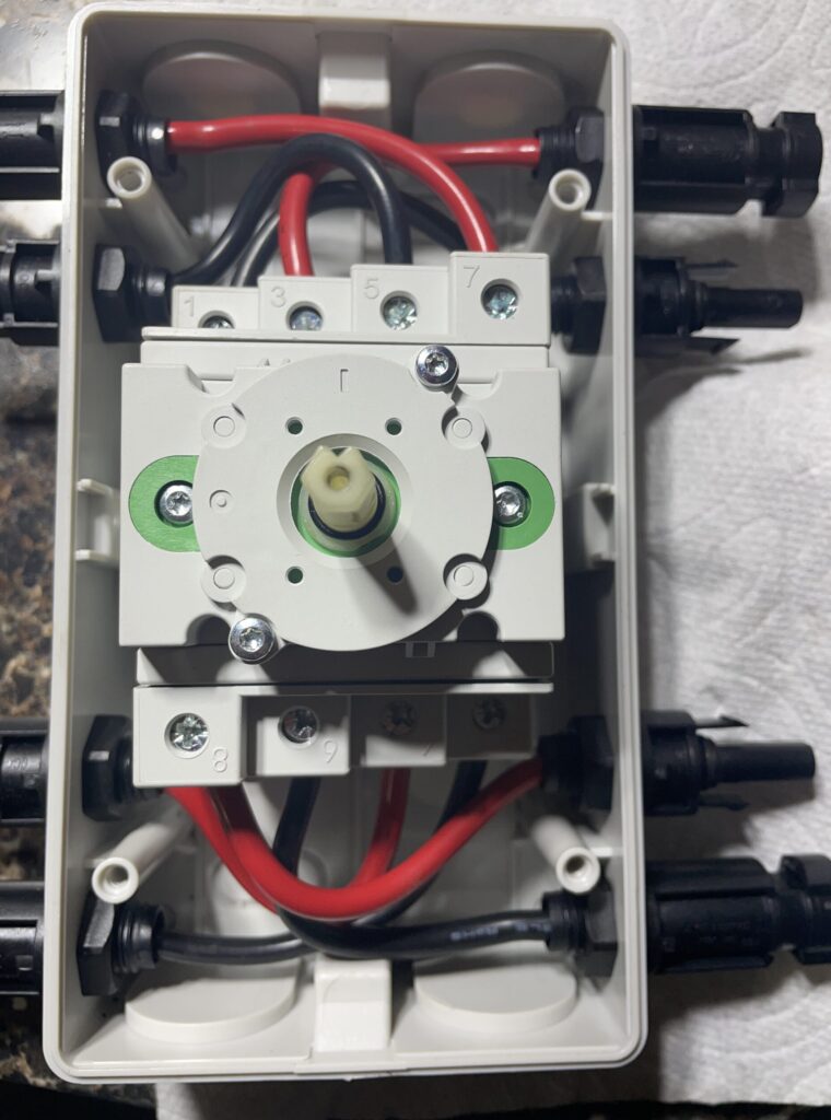
Note that terminal 7 connects to terminal 8, and 5 to 9 when the switch is on. Surprise, surprise–not where you’d guess by just looking at the switch. The terminals are 180 degrees apart. And now you know why.
In the next video and post lets ruin some of these by taking one of each apart and see what’s in the guts.