
I’m starting a new, very ambitious project. I certainly don’t need a new project–I’m turning 80 in January, with my current list of unfinished projects I’ll need to live to be about 120. But I don’t really have a choice. My wildfire Resilience/energy management system has hit a major snag–my EG4 18K PV is dead–sort of. The DC bus reads about zero ohms–dead short. If I connect the battery it immediately trips the breaker (of course). The MPPTs still work, when the sun is out the panels feed in power and the inverter wakes up. But there’s no battery connection. I’ve probably got a bunch of dead MOSFETs and when they die they can either die open or shorted. I’m just guessing. I contacted EG4, and a tech stepped me though some diagnostics, but during the diagnostics when I sent pictures of the connections the tech realized I had a non-standard connection to the load output. I haven’t had much luck hiring an electrician. With all the work rebuilding after the Lahina and upcountry fires on Maui, everyone is as busy as they want to be. Working with some goofball amateur to do a fully permitted modification to a sprawling house that would take it partly off-grid clearly looks like a tar-baby to any electrician who hasn’t done a lot of solar installations. So I had a temporary connection feeding 120V to keep a portable Ecoflow Delta Pro charged, whose only function was providing uninterruptible power to my internet system. I should have just plugged the thing into the wall, but I had this entire PV power system right on the other side of the wall. So I ran a lead directly from one side of the load terminals to the an outlet box and connected the other side to neutral. And because it was completely off-grid with no service box I didn’t want neutral floating, so I jumpered it to ground. Clearly non-standard wiring, but really not much different in end result to wiring it to a service box and doing the same thing in the box. So the tech killed the warranty. I really can’t argue with that, and I didn’t. I asked them to explain how that could possibly kill the DC bus, but I don’t really have a leg to stand on.
I could ship the inverter back to them and pay for them to repair it, but I haven’t even asked about that possibility–shipping anything big and heavy to Maui is astronomically expensive, and it would have to take the trip twice. I probably need a board replaced, but internal parts are not available–EG4 doesn’t sell them. I checked with Luxpower who actually make the 18K PV, and they don’t have a distributor other than EG4 who could handle selling me a board. I consider all these to be reasonable business decisions. They don’t want people sticking their hands in a system that could easily kill them. And they need to administer warranty rules consistently. It’s inconvenient for me, but I can’t fault the decisions. But nothing stops me from diving in and trying to fix it myself at the component level. In fact, it’s a cool opportunity. I have most of the diagnostic tools I need here in Maui. Yeah, I”m still a geek, even in paradise. The only thing I’m lacking is a variable DC power supply and I don’t have a differential probe for my little scope, but the scope is isolated (powered by a wall wart) so I might be OK there. Fortunately variable power supplies aren’t expensive these days.
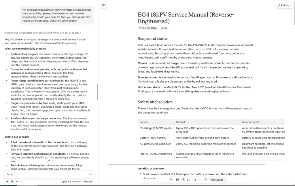
So I’m fully engaging Claude in the project. AI is made for this kind of goofiness. I already used Claude to integrate all the installation manual and ancillary manuals into one highly indexed, highly hyperlinked manual. It’s super handy. So now I’m going to use Claude to reverse engineer a repair manual. Here’s a screen capture of the start:
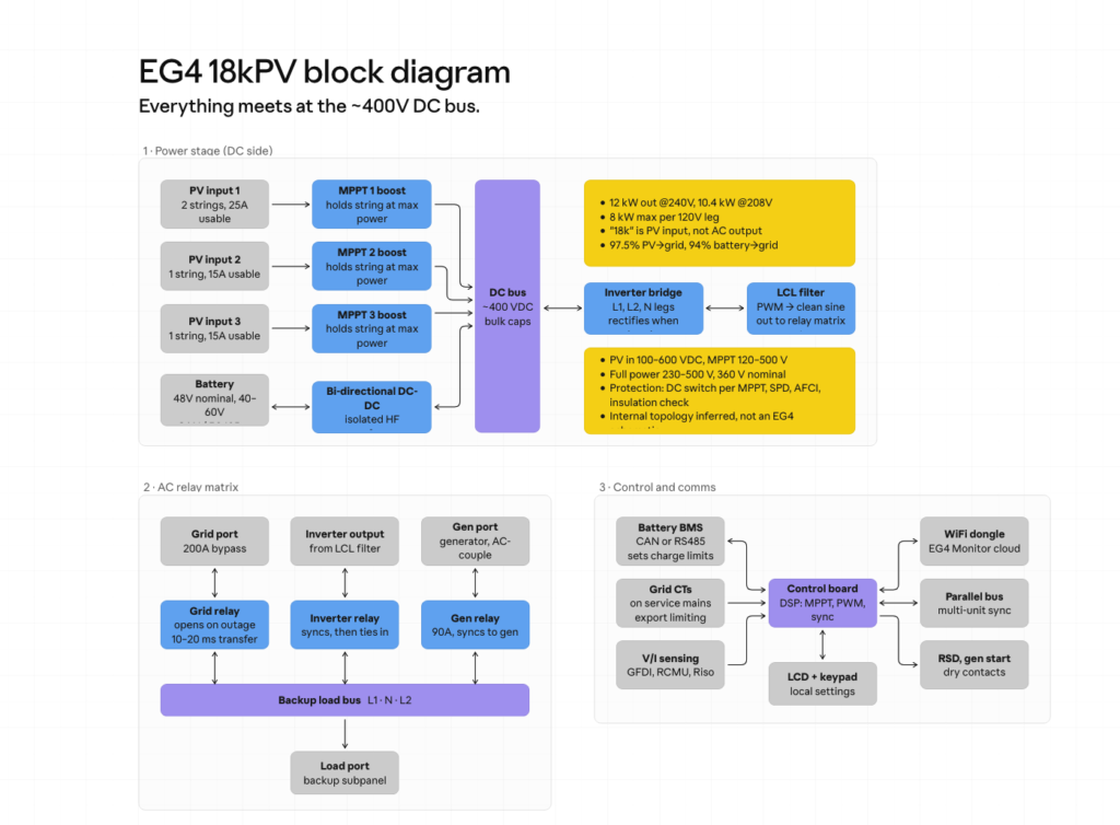
And a screen capture of the presumed block diagram to how the system probably works. As we work through the teardown and the test and measurement part of the troubleshooting the block diagram will change and be deeply updated. each of the blocks is linked to a system description. In the actual block diagram (instead of this simple screen capture) the blocks are hyperlinked to everything we know about each system component. right now it’s just best guess, but over time it will get useful
Here’s the written part of the manual so far–safety requirements, manual structure, and open questions: Scope and status
This is a board-level service manual for the EG4 18kPV, built from teardown, measurement and datasheets. It is original documentation, with no EG4 or Luxpower material reproduced. Status: pre-teardown; the architecture and board functions below are hypotheses until confirmed by photos and measurements.
Covers: isolation and discharge, board inventory and interconnects, connector pinouts, power-stage component identification, test points with expected values by operating state, and fault-tree diagnostics.
Does not cover: trace-level schematics of multilayer boards, firmware, or calibration data. Control-board faults are diagnosed to the board, not repaired.
Unit under study: the Maui 18kPV, faulted Nov 2026 (see Unit identification). Confirmed findings are marked confirmed; everything else is a working hypothesis.
Safety and isolation
The unit has four energy sources. Treat the internal DC bus as live until measured dead at the capacitor terminals.
| Source | Hazard | Isolation point |
|---|---|---|
| PV strings (3 MPPT inputs) | Up to 500 V DC open-circuit; live whenever the array is lit | Array-side disconnect or combiner; the inverter’s PV switch alone leaves the input conductors live |
| Battery (48 V nominal) | Very high fault current; arc and burn hazard | Battery breaker plus external disconnect |
| AC ports (Grid, Load, Gen) | 240 V AC, including backfeed from other sources | Upstream breakers; lift the conductors if backfeed is possible |
| Internal DC bus capacitors | Stored charge at bus voltage after all inputs are removed | Wait out the label’s discharge time, then measure |
Isolation procedure
- Shut down from the LCD, then open the battery breaker and the external battery disconnect.
- Open the PV disconnects. If testing in daylight, open them at the array side, or cover the array.
- Open the Grid, Load and Gen breakers. Lock and tag every isolation point.
- Wait at least the discharge time printed on the unit’s label.
- Live-dead-live check with a CAT III meter: verify the meter on a known source, measure each port and the bus capacitor terminals, then re-verify the meter.
- If a capacitor bank holds voltage, bleed it through a power resistor with insulated leads. Never short it.
Working rules
- Probing on the high-voltage side while powered requires a differential probe or an isolated scope. A grounded scope clip on the bus is a short circuit.
- First power-up after any repair is on a current-limited bench supply, never on PV or battery.
- One hand on the probe, the other clear, whenever anything is energized.
Unit identification
The inverter is manufactured by Luxpower for EG4; its monitoring identifies as “Luxpower LXP” over MQTT.
| Field | Value |
|---|---|
| Model | EG4 18kPV-12LV |
| Serial number | |
| Manufacture date | |
| Firmware (DSP / ARM / LCD) | |
| Luxpower equivalent model | |
| Installation | Off-grid, Maui guest-house structure; no service panel; neutral-ground bond on the bus; added 120 V L1-N circuit for EcoFlow charging |
Fault history
| Date | Event |
|---|---|
| Nov 2026 | Battery breaker trip. Faults: Bat Open, Vbus over range. |
| Nov 2026 | EG4 support: battery bus shorted inside the inverter; warranty denied over the off-grid wiring. |
| Nov 2026 | Luxpower declined to sell a replacement board directly; EG4 declined to supply one. |
| 2026-11-14 | Monitoring still live: PV1 reads 397.6 V (open circuit), PV2 and PV3 read 0.1 V, AC output about 1.5 V, battery SOC frozen at 1% since Nov 12. Control board, PV voltage sensing and the comms dongle are alive. |
Naming convention
Every photo, measurement and table entry uses the same identifiers, so the log can be sorted straight into the manual.
| Item | Format | Example |
|---|---|---|
| Board | Short code, assigned at teardown | CTRL, DCDC, INV, MPPT, AUX, COMM, LCD |
| Component | Board + silkscreen reference | DCDC-Q3 |
| Component, no silkscreen | Board + X + number we assign | DCDC-X12 |
| Component pin | Component + pin name | DCDC-Q3.D, DCDC-Q3.G |
| Connector | Board + J + number | CTRL-J4 |
| Connector pin | Connector + pin | CTRL-J4.7 |
| Test point | Board + TP + number | INV-TP2 |
| Photo file | Date_Board_Side_Seq | 20261120_DCDC_top_003.jpg |
Pin 1 of each connector is identified from the silkscreen or the keyed shell, and photographed before the connector is unplugged.
Operating states
| State | Condition |
|---|---|
| S0 | Unpowered, discharged, verified dead |
| S1 | Bench supply, current-limited, to one board or rail |
| S2 | PV only, battery isolated (No Battery setting) |
| S3 | Battery only |
| S4 | Full operation |
Every measurement names its state. A reading without one is not used.
Photo checklist
Photograph each layer before disturbing it. Shoot square-on in diffuse light, with a ruler in frame.
- Exterior: all faces, the rating label and the serial label
- Wiring compartment with conductors still landed, then each terminal block after lifting them
- Cover removed: whole interior from directly above, then each quadrant
- Every connector and harness in place, before unplugging, with pin 1 visible
- Each board, top and bottom, whole board in one frame
- Each power device: a macro of its marking, readable in the image
- Each IC near the power stages (gate drivers, current sensors, optocouplers, PWM controllers): a macro of its marking
- Fuses, shunts and magnetics, with any printed values
- Any damage at close range: discoloration, cracked packages, bulged capacitors, carbon tracks
- Board part numbers and revision codes, usually on the silkscreen or a sticker
- Raking-light shots of the DC-DC board, to show traces and heat marks
- Each reassembly step in reverse, for the manual’s reassembly section
System architecture
[embed: node/c5340b7c-5170]
If the DC-DC converter is the only failed stage, isolating it leaves PV to bus to inverter intact. That is the premise of the No Battery test. Confirm each box and connection against photos, then update this drawing.
Board inventory
The codes and functions below are expected for a hybrid of this class. Rename, merge or add rows once the case is open.
| Code | Expected function | Board P/N and rev | Photos | Condition |
|---|---|---|---|---|
| CTRL | DSP and ARM controllers, sensing, protection logic | |||
| MPPT | PV input boost stages, one per MPPT | |||
| DCDC | Bidirectional isolated converter between battery and the high-voltage bus | Suspect | ||
| INV | Inverter bridge, output filter, current sensing | |||
| RELAY | Grid, Load and Gen transfer relays | |||
| AUX | Auxiliary supplies for logic and gate drivers | |||
| COMM | Dongle port, battery CAN/RS485, CT inputs, parallel ports | |||
| LCD | Display and buttons | |||
| EMI | Input and output EMI filters |
Connector pinouts
External terminals first, then internal board-to-board connectors as they are photographed. One row per pin; the measured column names its state.
| Connector | Pin | Signal | Measured (state) | Notes |
|---|---|---|---|---|
| PV1 | + / – | String 1 | 397.6 V (S2, open circuit, 2026-11-14) | From monitoring, not yet probed |
| PV2 | + / – | String 2 | 0.1 V (2026-11-14) | Disconnected or open? |
| PV3 | + / – | String 3 | 0.1 V (2026-11-14) | Disconnected or open? |
| BAT | + / – | 48 V battery | Suspected short internally | |
| GRID | L1, L2, N | Not used in this install | ||
| LOAD | L1, L2, N | Off-grid output | ||
| GEN | L1, L2, N | |||
| BMS | CAN / RS485 | Battery comms | ||
| CT | CT1, CT2 | Current transformers | ||
| Dongle | — | WiFi monitoring | Working (MQTT data current) |
Power-stage component register
One row per power device, gate driver, current sensor and bus capacitor bank. Part identity comes from the marking macro plus datasheet; the diode-mode reading is taken in S0.
| Ref | Marking | Identified part | Type | Rating (V / A) | Function | Diode mode (S0) | Status |
|---|---|---|---|---|---|---|---|
| DCDC-Q1 |
Diode-mode convention: record gate-source, drain-source with red on source (body diode, normally 0.3 to 0.7 V), and drain-source with red on drain (normally open). A reading near 0 V both ways means a shorted device.
Test points and expected values
Expected values are filled in only after they are measured on a working section or confirmed from a datasheet. Until then the column stays blank, not estimated.
| Test point | Description | S0 | S1 | S2 | S4 | Source of expected value |
|---|---|---|---|---|---|---|
| HV bus (+ to -) | Main DC bus at the capacitor bank | 0 V | ||||
| BAT terminals | Inverter side of the battery input | |||||
| AUX rails | Logic and gate-driver supplies |
Diagnostics: Bat Open / Vbus over range
Goal: find what is shorted, and decide whether the high-voltage side is intact enough to run PV-only with the battery converter isolated. Work unpowered (S0) until the fault is located.
- Visual. Inspect the DC-DC board and the battery input path for burn marks, cracked packages, bulged capacitors, open fuses and carbon tracks. Photograph everything found.
- Battery input resistance. Measure across the inverter’s BAT terminals, both polarities. A near-zero reading both ways confirms the short. A reading that climbs slowly is capacitor charging, not a short.
- Battery-side fuses and shunt. Check continuity of every fuse between the BAT terminals and the DC-DC board.
- Isolate the DC-DC board. Disconnect it from the high-voltage bus and from the battery input, if it connects by plug or bus bar. Repeat step 2 on each side to locate the short.
- Power devices in circuit. Diode-mode every device on the DC-DC board per the register convention. Lift any suspect and re-test it out of circuit.
- High-voltage bus. With the DC-DC board disconnected, measure resistance across the bus capacitors. It should climb as they charge. Near zero means a second shorted path, so check the MPPT and INV stages before any PV test.
- Collateral damage. For every shorted device, check its gate resistor, gate-driver output and any snubber. Those usually fail with it.
- Decision. HV bus clean with DC-DC isolated → PV-only test (S2) with the No Battery setting, at low irradiance first and minimal load. HV bus shorted → trace the MPPT and INV stages before applying any power.
Open point: Vbus over range may have been a real overvoltage during the event, or a bus-sensing fault. Record the bus reading the LCD reports during the first S2 test and compare it against a meter on the capacitors.
Measurement log
Every reading goes here first, newest at the top. Confirmed values are then copied into the pinout, register and test-point tables.
| # | Date | State | Point | Red / Black | Mode | Value | Photo | Notes |
|---|---|---|---|---|---|---|---|---|
| 1 | 2026-11-14 | S2 | PV1 | Monitoring | DC V | 397.6 V | — | Open circuit via MQTT; PV2 and PV3 at 0.1 V |
Parts, repairs and open questions
Board-level replacement is closed: Luxpower sells boards only through EG4, and EG4 will not supply one. The repair path is component-level, so the register above is the critical document.
Sourcing routes
- Discrete power devices, gate drivers and passives from distributors, identified from the register
- A salvage DC-DC board from a secondhand or damaged 18kPV
- A board from a Luxpower-branded sibling, if it proves physically and electrically identical
Repair log
| Date | Ref | Action | Part used | Result |
|---|
Open questions
Does the No Battery setting run the Load port off-grid on this firmware, and how does it handle motor inrush?
Is the DC-DC converter a separate board, and how does it connect to the HV bus?
Which Luxpower model is the 18kPV built from, and do its boards interchange?
Is the board part number shared with the 12kPV?
Are PV2 and PV3 disconnected on purpose?
Was Vbus over range a real overvoltage or a sensing fault?